Vision Solution Design
Before you deploy the application, you need to first design the vision solution and select the camera model, IPC model, camera mounting mode, robot communication mode, and more according to the actual needs of your project. A good design helps to quickly deploy a 3D vision–guided robotic application.
During the design phase of a 3D vision–guided robotic application, you need to complete the following steps:
Select Camera and Accessories
Mech-Eye industrial 3D camera is a high-performance camera developed by Mech-Mind. It features high accuracy, fast data acquisition, resistance to ambient light, and high-quality imaging and can generate high-quality 3D point cloud data of a variety of objects. Mech-Mind offers full model options to meet the needs of ambient light resistance, high accuracy, large field of view, high speed, and small size at different distances.
-
In real practice, please select the appropriate model according to the working distance, field of view, and accuracy of the camera.
To select the appropriate camera model, follow these steps:
-
Use the 3D Camera Selector to filter the appropriate model(s) according to the dimensions of the target object.
-
If there are multiple models that meet your requirements, select the most appropriate one according to Characteristics and Suitable Applications. Please contact Mech-Mind pre-sales engineers or sales for assistance.
-
-
Besides selecting a camera model, you also need to select optional accessories according to the actual project requirements, such as the power module, camera Ethernet cable, and calibration board. For details, refer to Camera Accessory Selection.
Determine Camera Mounting Mode
You can determine the camera mounting mode based on the relative position of the camera to the robot and the needs of the overall cycle time. The following table shows two common camera mounting modes.
Mounting mode |
Eye to hand (ETH) |
Eye in hand (EIH) |
|---|---|---|
Description |
The camera is mounted on a camera mounting frame independent of the robot. |
The camera is mounted on the last joint of the robot and moves with the robot. |
Illustration |
|
|
Characteristics |
|
|


In addition, to expand the camera’s field of view and improve the quality of the overlapped point cloud, a project may have two or more cameras installed for one station, which is called Eye to eye (ETE).

Regardless of the camera mounting mode you choose, you will need a camera mounting frame to mount the camera. For the design description of the camera mounting frame, please refer to Camera Mounting Frame Design.
Select IPC Model
Mech-Mind IPC provides the standard operation environment for Mech-Mind’s software products and therefore can maximize the function and performance of the software.
Please select the appropriate IPC model according to the application scenarios, technical parameters, and performance technical specifications of IPCs. The performance technical specifications of the IPCs are shown in the table below.
| Technical specification | Application scenario | Mech-Mind IPC STD | Mech-Mind IPC ADV | Mech-Mind IPC PRO |
|---|---|---|---|---|
Number of Mech-Vision projects that can be run simultaneously |
Scenarios using Standard Interface/Adapter communication (without the Path Planning Step) |
≤5 |
≤5 |
≤5 |
Scenarios using Standard Interface/Adapter communication (with the Path Planning Step) |
≤5 |
≤5 |
≤5 |
|
Scenarios using Master-Control communication (using the Mech-Viz software) |
≤5 |
≤5 |
≤5 |
|
Scenarios where the 3D vision solution uses 3D matching for recognition |
≤5 |
≤5 |
≤5 |
|
Scenarios where the 3D vision solution uses 3D matching and 2D deep learning for recognition |
≤2 |
≤2 |
≤4 |
|
Number of cameras supported per solution |
≤2 |
≤2 |
≤2 |
|
Number of supported deep learning models per solution |
≤5 (CPU) |
≤5 (GPU) |
<8 (GPU) |
|
Number of supported robots per solution (Master-Control communication) |
1 |
1 |
1 |
|
Number of communication modes supported per solution |
1 |
1 |
1 |
|
Number of clients that can be connected simultaneously per solution (Standard Interface/Adapter communication) |
≤4 |
≤4 |
≤4 |
|
If you use your own computer or laptop (“non-standard IPC” for short) as the industrial personal computer (IPC), please refer to Non-standard IPC Setup to make sure the non-standard IPC meets the system configuration requirements and complete the corresponding settings.
Select Robot and Robot Flange
Factors such as robot payload, robot reachability, and communication mode should be considered when selecting a robot model. For details, refer to Robot Model Selection.
A robot flange is a standard interface mounted on the last joint of the robot arm for connecting various tools or devices. In 3D vision–guided robotic applications,to facilitate the mounting of the calibration board on the robot end, Mech-Mind provides robot flanges in the following models. Please select the appropriate flange according to the actual requirement.
| Image | Model | Dimensions (mm) |
|---|---|---|
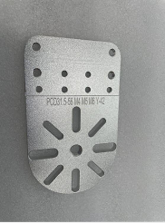
|
RF-S: Robot Flange (Small) |
106 x 64 x 5 |
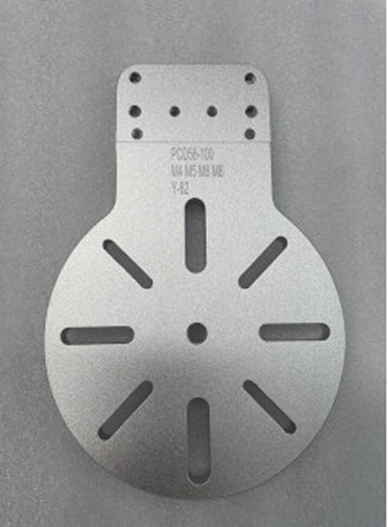
|
RF-M: Robot Flange (Medium) |
174 x 120 x 8 |
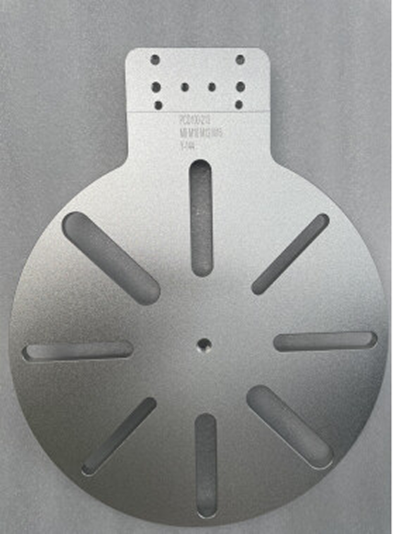
|
RF-L: Robot Flange (Large) |
296 x 240 x 8 |
Select Robot Communication Mode
The interface communication mode is usually suitable for practical applications on the production line, providing more flexible functionality as well as a shorter cycle time. The Master-Control communication mode is usually applied in the testing phase of a project for quick verification of the picking effect.
| If you choose to use the interface communication mode and need to use Mech-Viz to obtain the planned path, you need to obtain the authorization for the Mech-Viz software. |
For more information about how to select the communication mode, please refer to the section Communication Mode Selection. For more information about the communication modes, please refer to the section Communication Basics.
Determine Whether to Use Deep Learning
Please refer to the Select Deep Learning Solution section to determine whether to use deep learning in your vision solution.
| If the vision solution needs to use deep learning to assist recognition, you need to obtain the authorization for the Mech-DLK software. |
3D matching may not solve the following problems effectively during the vision recognition process. In this case, you need to use deep learning:
| No. | Challenges to traditional methods | Illustration |
|---|---|---|
1 |
The surfaces of the objects are highly reflective, and the quality of the point cloud is poor. |
|
2 |
The geometric features on the target object’s point cloud are fewer, and the number of feature points in the point cloud is lower. |
|
3 |
When the target objects are neatly arranged and closely fitted, it is difficult to identify the point clouds of individual objects or the point clouds of individual objects may be misidentified. |
|
4 |
The object feature is only visible in the color image but not visible in the point cloud. |
|
5 |
The project has a high requirement for the vision cycle time. When there is a large number of objects, the matching time using the point cloud model can be long. By using deep learning to first filter a batch of target objects and then performing matching, the time required for matching can be shortened. |
|


Clarify Project Accuracy Requirements
Before actually deploying a vision solution, you need to confirm the accuracy requirements of your project (e.g., ±3 mm) and determine the accuracy expectations and objectives of your application. Normally, the picking accuracy of ±3–5 mm can meet the requirements of common projects.
Confirm Software License Form and Required Products and Features to Authorize
Mech-Mind uses Sentinel LDK as the licensing system for its software products. This license system supports two encryption methods: Software Licensing Device and Software Licensing Code. Please contact Mech-Mind to confirm the required authorization form (encryption method).
To ensure that the vision solution can run normally, the Software Licensing Device or Software Licensing Code should contain the authorization for corresponding products or features.
| Product/feature authorization | Description |
|---|---|
Mech-Vision 2.0+ |
Mandatory product authorization. This authorization is required when you run Mech-Vision 2.0+. |
Mech-Viz 2.0+ |
Optional product authorization. If you choose to use the interface communication mode and want to use Mech-Viz to obtain the planned path, you need to obtain this authorization. |
Determine Working Environment Requirements
When designing a vision solution, it is crucial to ensure that components operate under the appropriate environmental conditions. This not only affects the performance of the system but also directly affects the lifespan and reliability of the hardware.
Before installing and using the vision system, thoroughly check the specific requirements of the vision system hardware for environmental conditions, including but not limited to the following aspects:
-
Ambient temperature
Check the operating temperature range of hardware (mainly cameras and IPCs) to ensure that they can operate normally within the ambient temperature range. If necessary, air conditioners, heaters, or insulation can be used to adjust the ambient temperature.
For the operating temperature range of the camera, please refer to Camera Technical Specifications. For the operating temperature range of the IPC, refer to IPC Technical Specifications.
-
Ambient humidity
Check the operating humidity range of hardware (mainly cameras and IPCs). Measures should be taken to avoid condensation, corrosion, or short circuits caused by high humidity.
For the operating humidity range of the camera, please refer to Camera Technical Specifications. For the operating humidity range of the IPC, please refer to IPC Technical Specifications.
-
Vibration tolerance
The vibration resistance and impact resistance of the 3D cameras provided by Mech-Mind meet this standard. For specific information about the camera’s vibration tolerance and shock tolerance, refer to Camera Technical Specifications.
Ensure that the vibration intensity of the operating environment of the vision system does not exceed the requirements of the above standards. If the camera continues to experience vibrations exceeding this range, its performance may be degraded. Vibration significantly exceeding this range may lead to camera damage or production line downtime. Mech-Mind shall not be liable in any way for such circumstances.
-
Protection against dust and pollutants
Mech-Mind cameras feature a high protection rating, and can effectively prevent dust or particulate matter from entering the equipment.
To ensure image quality, you need to clean the body and windows of the camera regularly.
-
Electromagnetic interference (EMI) protection
Ensure that the equipment is installed away from strong electromagnetic interference sources (such as large motors, wireless communication devices, etc.) to prevent issues such as frame loss, missing depth maps, and other data acquisition anomalies.