Vision Project Configuration
Before using this tutorial, you should have created a solution using the “Loading Neatly Arranged Target Objects” case project in the Robot Communication Configuration section.
In this tutorial, you will first learn the project workflow, and then deploy the project by adjusting the Step parameters to recognize the target objects’ poses and output the vision result.
Introduction to the Project Workflow
In this tutorial, you need to configure the vision project with Mech-Vision. The process of how to configure a vision project is shown in the figure below.
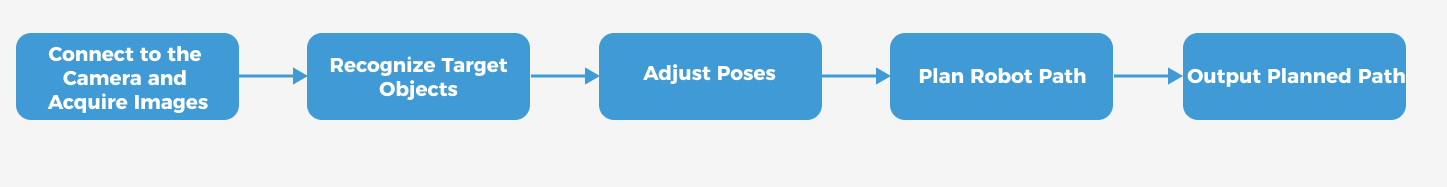
The phases of the vision project configuration process are explained below.
| Phase | Used software | Description |
|---|---|---|
Connect to the Camera and Acquire Images |
Mech-Vision |
Connect to the camera through the Mech-Vision’s “Capture Images from Camera” Step for image capturing purposes. |
Recognize Target Objects |
Mech-Vision |
Perform a series of vision processing (point cloud preprocessing, 3D matching, etc.) on image data through the Mech-Vision’s “3D Target Object Recognition” Step to quickly recognize target objects. |
Adjust Poses |
Mech-Vision |
Use the “Adjust Poses V2” Step of the Mech-Vision software to transform the reference frame, adjust poses, sort poses, or filter poses output by the “3D Target Object Recognition” Step. |
Plan Robot Path |
Mech-Vision |
The “Path Planning” Step of the Mech-Vision software will dynamically plan a collision-free robot motion path based on the target object poses adjusted in the previous step. |
Output Planned Path |
Mech-Vision |
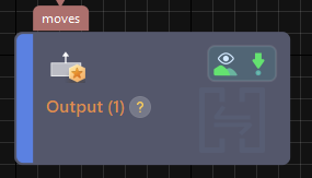
Upon receiving the Standard Interface command from the robot (used in this tutorial) or the PLC, the “Output” Step of Mech-Vision returns the planned collision-free robot motion path.
|
Adjust Step Parameters
In this section, you will deploy the project by adjusting the parameters of each Step.
| The project in this section is the “Vis_Target_Objects_Recognition” project in the “Loading Neatly Arranged Target Objects” solution. |
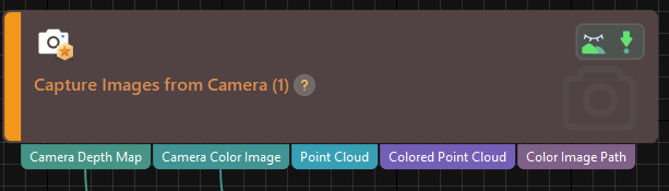
Capture Images from Camera
Step name |
Capture Images from Camera |
|---|---|
Phase |
Connect to the Camera and Acquire Images |
Illustration |
|
Description |
Connect to a real camera and configure relevant parameters to ensure that the camera can capture images normally. |
-
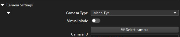
In the Graphical Programming Workspace of Mech-Vision, select the Capture Images from Camera Step, and click Select camera on the Step Parameters tab.
-
In the prompted Select camera and calibration parameter group window, click the
 icon to the right of the camera serial number. When this icon turns into an
  icon, the camera is connected successfully.
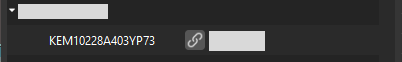
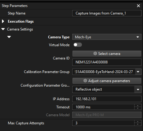
After the camera is connected, click the Select parameter group button and select the calibrated parameter group with ETH/EIH and date.
The calibration parameter group selected here is the one generated after the hand-eye calibration is completed. -
After the camera is connected and the parameter group is selected, the calibration parameter group, IP address, and ports of the camera will be obtained automatically. Make sure that Configuration parameter group is set to “Reflective object”.
-
Click the Single Step Execution button of the Capture Images from Camera Step to trigger image capturing, double-click the “Camera Depth Map” and “Camera Color Image” data streams of the Step, and check whether the images were successfully captured from the camera in the Debug Output window.
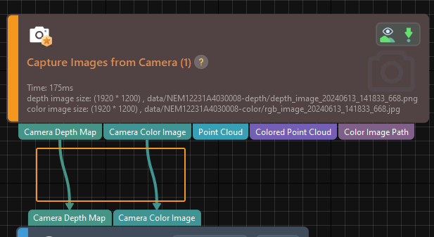
-
If you can see a normal depth map and color image in the Debug Output window, the Mech-Vision software has successfully connected to the real camera and can capture images normally.
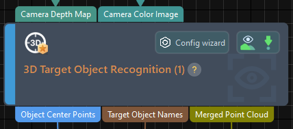
3D Target Object Recognition
Step name |
3D Target Object Recognition |
|---|---|
Phase |
Recognize Target Objects |
Illustration |
|
Description |
You need to set point cloud preprocessing parameters, make target object models in the target object editor, select the target object, set recognition parameters, and configure output ports. |
The "3D Target Object Recognition" Step provides a built-in visual "3D Target Object Recognition" tool. With the wizard, you can easily recognize target object poses in only three steps.

You can start parameter adjustment by opening the "3D Target Object Recognition" tool in either of the following ways.
-
Click the Config Wizard button on the Step block in the Graphical Programming Workspace.
-
In the Step Parameters tab, click the Config wizard button.
Point Cloud Preprocessing
Point cloud preprocessing converts the acquired image data to point clouds, detects edge point clouds, and filters out point clouds that do not meet the rules by setting valid point cloud recognition regions, thus improving subsequent recognition efficiency.
In this step, you need to set an effective recognition region to keep the interference factors out of the region to improve recognition efficiency. The recognition area should cover the pallet and the target objects on it. It should be 20 to 30 mm wide to accommodate the effects of small variations in the pallet placement.
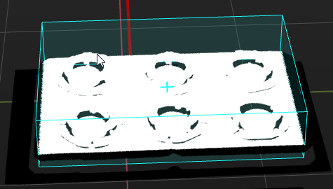
Usually, keep the default values of other preprocessing parameters. If there are many noises in the scene, you can try adjusting relevant parameters. For details, refer to Point Cloud Preprocessing.
| After parameter adjustment, you can click the Run Step button in the Preview preprocessing result area, and confirm that the preprocessing effect meets expectations in the Visualizing Space. |
Target Object Selection and Recognition
|
Make the Target Object Model
In this tutorial, please refer to Set the Pick Points by Jogging the Robot, and Generate the Point Cloud Model Based on the Acquired Point Cloud to make the point cloud matching model for the target object.
|
For only simulation purposes, you can use the following pose as the poses of the pick point set by teaching:
When setting the poses of the pick point, select "Euler angles" as the pose orientation. |
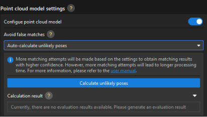
Precautions:
-
In this example, the target objects are symmetrical. To avoid errors caused by rotating before picking, you need to configure the Avoid false matches parameters to filter out matching poses with large angle deviations from the model. In the 3 Edit model tab of the target object editor, in the Point cloud model settings area, enable the Configure point cloud model option, and set the Avoid false matches parameter to “Auto-calculate unlikely poses." The calculation results are used to quickly filter out poses that do not meet the angle requirement for subsequent point cloud matching.
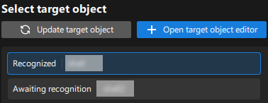
After the target object model is created, close the Target Object Editor window to return to the "3D Target Object Recognition" tool interface, and click the Update target object button. If there is only one target object model in the target object editor of the solution, the tool will automatically select the target object model. If there are multiple target object models in the target object editor of the solution, please select the target object model to use.
Set Matching Parameters
-
In the Recognize target object area, enable the Auto-set matching mode option for the matching mode.
-
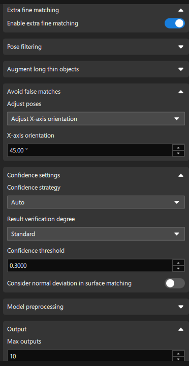
Enable Advanced mode and Extra fine matching.
Due to the high picking accuracy requirements of this application, you need to enable Advanced mode and Extra fine matching to further improve matching accuracy. -
Add the "Avoid false matches" setting: Select “Filter out unlikely poses” and set Range to 45°.
Since the target objects in this application are 90° symmetrical, the Range parameter should be set to 45° to make the output matching poses closer to the geometric center of the model. Matching poses with model angle deviations greater than plus or minus 45° are removed, thus reducing picking errors. -
Modify the confidence threshold: Set Confidence threshold according to actual needs, such as 0.6, to remove incorrect matching results.
-
Set Max outputs according to actual needs, such as 10. Minimize the number of outputs to reduce matching time while satisfying the path planning requirements.
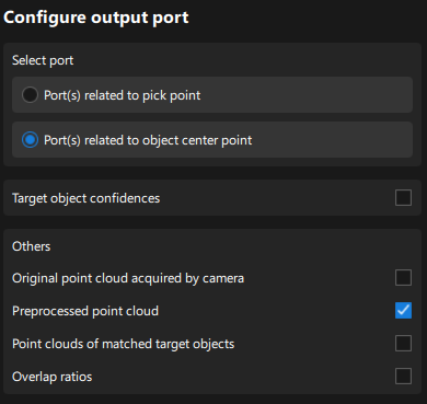
Configure Output Ports
Select the following output ports for subsequent path planning and collision detection:
-
Port(s) related to object center point
The types of output ports are described as follows:
-
Port(s) related to pick point: Suitable for target objects with multiple pick points that need to be filtered.
-
Port(s) related to object center point: Suitable for symmetrical target objects that require orientation adjustment of the object center point.
-
-
Preprocessed point cloud (for subsequent robot path planning)
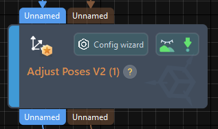
Adjust Poses V2
Step name |
Adjust Poses V2 |
|---|---|
Phase |
Adjust Poses |
Illustration |
|
Description |
Set parameters to transform poses, adjust poses, sort poses, and filter poses. |
After obtaining the target object pose, you need to adjust the pose. The processing procedure is as follows.

With the built-in pose adjustment tool in Mech-Vision, you can easily adjust object poses and optimize the picking sequence. You can start parameter adjustment by opening the pose adjustment tool in either of the following ways.
-
Click the Config Wizard button on the Step block in the Graphical Programming Workspace.
-
In the Step Parameters tab, click the Config wizard button.
Follow these steps to adjust parameters:
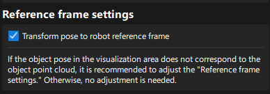
-
Transform poses: In the Pose adjustment tab, transform poses from the camera reference frame to the robot reference frame.
-
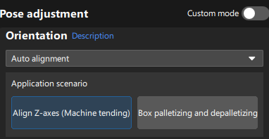
Adjust poses: In the Pose adjustment tab, set Orientation to “Auto alignment” and select the Align Z-axes (Machine tending) scenario. This operation aligns the Z-axis orientation of the pose with the positive direction of the robot reference frame as much as possible.
-
Sort poses: In the Processing rules tab, select the “Sort by Z shape on plane” sorting type, and set the reference pose with the manipulator. Select “Positive X-axis of reference pose” for Row direction and “Positive Y-axis of reference pose” for Column direction, and set the row interval according to needs.
In this application, since the target objects are neatly arranged, the robot picking of the target objects in a “Z” order from the upper left corner has the best performance. 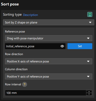
-
Filter poses by angle: In the Processing rules tab, filter out poses that are obviously unpickable according to their Z-axis directions, reducing the time spent on path planning for the "Path Planning" Step.

-
Filter out poses out of ROI: In the Processing rules tab, set an ROI to determine whether the poses are in the ROI and keep only the poses in the ROI.
The target region (3d_roi) is in the robot reference frame. To avoid filtering errors, you must reset the target region according to the actual extrinsic parameters.
-
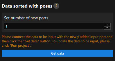
Set new ports: Set the Set number of new ports parameter to 1 to output the names of target objects corresponding to sorted poses for subsequent collision detection. Return to the graphical programming workspace and you will find a new input port and output port added to this Step for receiving and outputting the target object names. Please connect the input and output ports, return to the pose adjustment tool, and click the Get data button to confirm that the parameters have been obtained correctly.
Path Planning
This example obtains the planned path from the "Path Planning" Step of Mech-Vision. When using the Standard Interface communication mode, the project and the robot side need to cooperate to implement the 3D vision-guided robot picking and placing process. For details, refer to the instructions in the “Picking and Placing” section.