Topics: Common Issues with “3D Matching”
This section introduces how to troubleshoot matching issues caused by incorrect normals of the point cloud model and inconsistent reference frame of the point cloud to be matched.
Matching Problems Caused by Incorrect Normals in Point Cloud Models
Starting from Mech-Vision 2.0.0, the matching process has strict requirements on the normals of point cloud models. When the normals of a point cloud model are incorrect, it directly leads to matching failure. The following sections introduce the two abnormalities and their corresponding solutions.
Incorrect Normals Occur When Using STL Model to Generate Point Cloud Model
-
Symptom
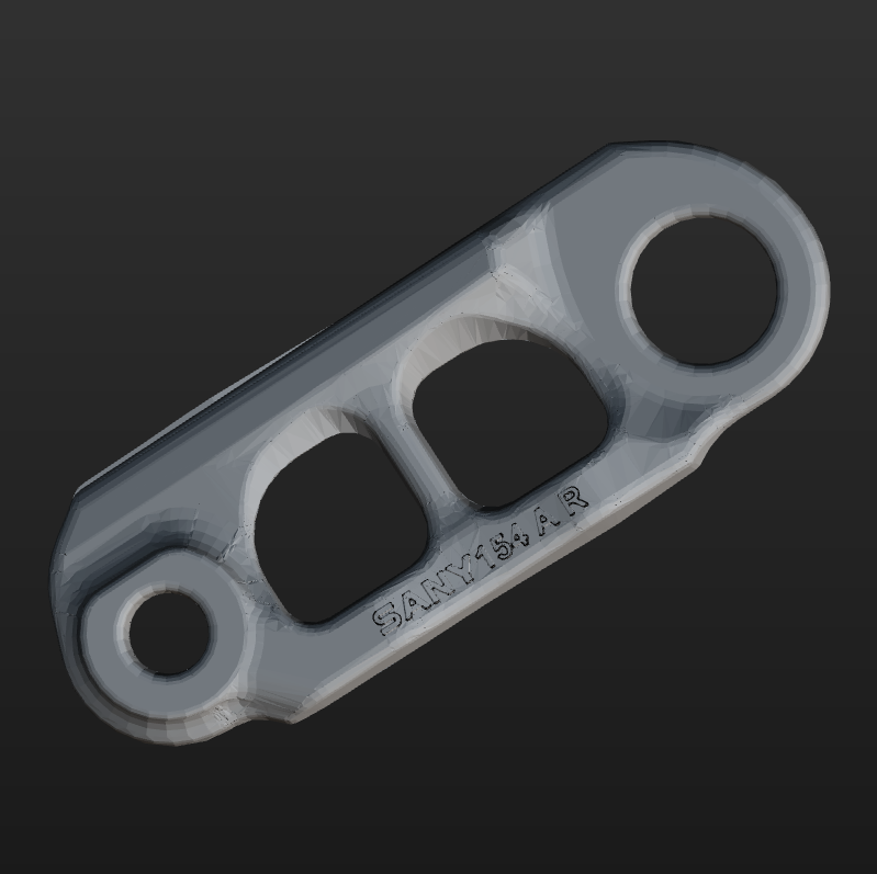
After the STL model was imported into the target object editor, some areas of the model were displayed in black, which usually indicates incorrect normals. Normally, the model should be rendered evenly
The table below shows examples of models with correct and incorrect normals.
Correct normals of the point cloud model Incorrect normals of the point cloud model 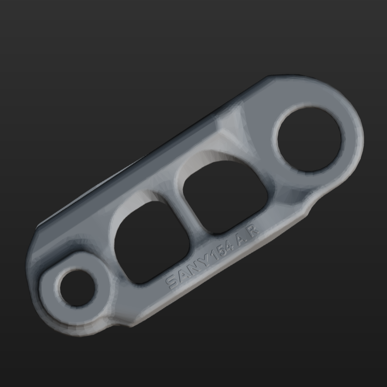

-
Solution
If the normals of the STL model are incorrect, you can use the “STL Model Normal Correction Tool” to repair the STL model.
For instructions on downloading and using the “STL Model Normal Correction Tool,” refer to Correct Normals of STL Model.
Incorrect Normals or Tangents Occur After Using Steps to Generate Point Cloud Models
-
Symptom
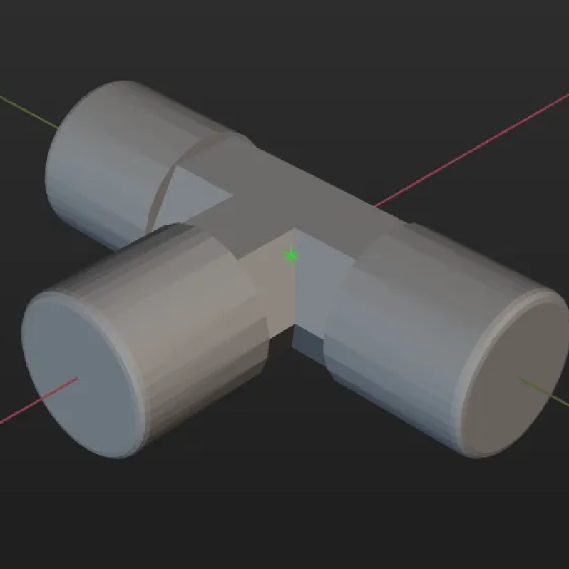
The edge point cloud model contains abnormal normals or tangents after being processed by Steps such as “Point Cloud Clustering,” “Get Highest-Layer Clouds,” etc.
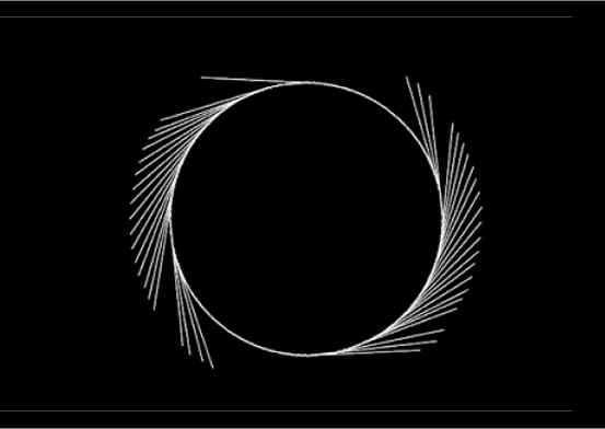
Correct normals of the edge point cloud model Incorrect normals of the edge point cloud model 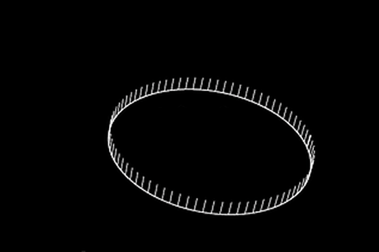
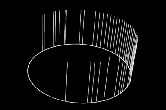
Correct tangents of the edge point cloud model Incorrect tangents of the edge point cloud model 
-
Solution
It is recommended to use the point cloud model generated by the Step directly for matching.
Matching Problems Caused by Inconsistent Reference Frame between Point Cloud Model and Point Cloud to Be Matched
When using the “3D Matching” Step, it is recommended to use the point cloud in the camera reference frame as the point cloud model, and ensure that the point cloud to be matched input to the “3D Matching” Step matches the reference frame of the point cloud model.
If the reference frame of the point cloud model does not align with that of the point cloud to be matched, the matching process will either fail or produce incorrect results. The specific issues are described below.
Remove Overlapped Poses Feature Filters Out Correct Matches
Once the “Remove Overlapped Poses” feature is enabled, when the overlap ratio between the point cloud of the target object in the camera reference frame and other point clouds above it exceeds the threshold, the pose of the overlapped target object will be removed.
However, in some cases, the correct matching result may be filtered out. The specific symptom is described as follows.
-
Symptom
After enabling the “Remove Overlapped Poses” feature in the “3D Matching” Step, the correct matching results were filtered out.
-
Possible Cause
When the point cloud of the target object is in the camera reference frame, and the point cloud to be matched is in the robot reference frame, and there are multiple fine matching results, the correct matching results are filtered out.
-
Solution
During matching, ensure that the point cloud input to the “3D Matching” Step shares the same reference frame as the point cloud model.
Wrong or No Matching Result after Adjusting “Angle Threshold”
If the point cloud model generated by the STL model is used for matching, you can remove the invisible parts of the point cloud model by adjusting the parameter in the “3D Matching” Step to improve matching speed and accuracy. This parameter is under the Expert tuning level.
However, adjusting the “Angle Threshold” may also lead to incorrect matching results or no matching results. The specific symptom is described below.
-
Symptom
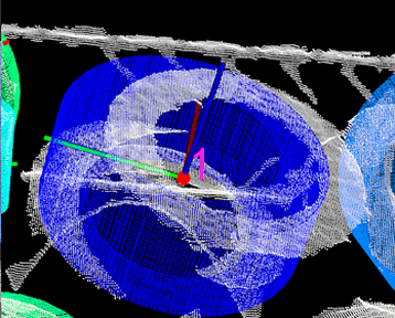
When Angle Threshold was set to 180°, the matching was successful. After adjusting the Angle Threshold, the matching results differed greatly from those before the adjustment, and the matching was incorrect.
Angle Threshold: 180° Angle Threshold: 135° 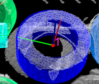
-
Possible Cause
The reference frame of the point cloud model and that of the target object was inconsistent.
-
Solution
During matching, ensure that the point cloud input to the “3D Matching” Step shares the same reference frame as the point cloud model.
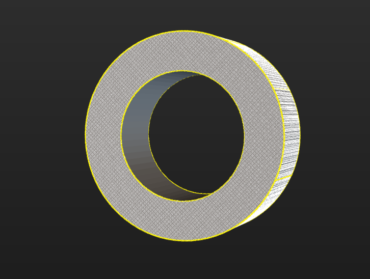
Matching Problems Caused by Point Cloud Loss on Inner Wall of Ring-Type STL Model
-
Symptom
When using Mech-Vision 2.x to generate a point cloud model based on the STL model of the ring, the point cloud model did not contain the point cloud of the inner wall of the ring, which reduced the confidence of the matching result.
-
Solution
This issue does not exist in Mech-Vision 1.8, so you can generate a complete ring point cloud with Mech-Vision 1.8 and use the “Read Point Cloud V2” Step in Mech-Vision 2.x to read the point cloud model for matching.