Guide to Improving Application Cycle Time
This section introduces how to improve the cycle time of each processing phase of a 3D vision-guided application.
Image Capturing
Reduce Exposure Time
While ensuring stable image quality, use the Mech-Eye Viewer software to minimize the times of exposure and shorten exposure time as much as possible.
-
For 3D images, the fewer the exposures and the shorter the exposure time, the shorter the cycle time.
-
For 2D images, the order of exposure modes by time consumption is: Flash < Timed < Auto. If 2D images are not needed or if permissible, Flash mode can be selected.
| Note that reducing exposure time cannot come at the expense of image quality. For recognizing metal pieces with complex structures or objects with many detail features, it is recommended to switch the 2D exposure mode and set two or three different 3D exposure times to capture images for more information. |
For adjusting 2D/3D exposure parameters, please refer to Improve Image Acquisition Speed and Camera Parameters Reference Guide.
In addition, if the exposure time is too long, you can consider adding an external light source to reduce the internal exposure time, thus improving the capture speed.
Update the Mech-Eye Viewer Software and Camera Firmware to the Latest Version
The software and camera firmware in the Mech-Eye Viewer are continuously improved by Mech-Mind to speed up the generation of depth maps and point clouds and the image capture speed of the camera.
Therefore, please upgrade your Mech-Eye Viewer and camera firmware to the latest version.
Adjust ROI and Depth Range
Set the ROI and Depth Range in the Mech-Eye Viewer according to the max FOV required by the project and remove unnecessary regions and depths, thus reducing the time for the camera to generate images.
For adjusting the ROI and depth range, please refer to Camera Parameters Reference Guide.
Ensure Camera Data Transmission Speed
The data transmission speed is displayed when the camera is running. The normal range is 700 to 800 Mbps.
After the camera is connected to the Mech-Eye Viewer software, you can check the data transmission speed of the connected camera in the data acquisition area.
If the data transmission speed is too low, make sure that the network switch, IPC, and other devices meet the industrial gigabit network transmission standards.
| The data transmission speed is only displayed when data is being transmitted. In addition, when the amount of data to be transmitted is small, the data transmission speed may be relatively low. |
Replace the Camera
In the vision solution design phase, besides considering the working range of the camera, you should pay attention to the differences in the typical capture time of different camera products. The specific capture time can be found in Camera Technical Specifications.
If the current cycle time of the application cannot meet the project requirements and other optimization measures cannot effectively improve the overall cycle time of the application, then you can consider replacing the camera to achieve improvement.
Vision Processing
Step Acceleration
Capture Images from Camera
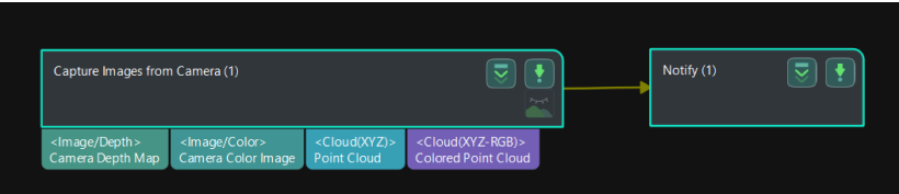
In Mech-Vision projects, the “Capture Images from Camera” Step is one of the most important Steps and usually takes about 40% of the time. Optimizing this Step can significantly improve the subsequent processing speed. Below are specific setup recommendations to reduce the runtime of this Step:
-
If the project does not require 2D processing, you can avoid connecting the “Camera Color Image” port. This can directly reduce the time for subsequent processing.
-
If the project does not use the Mech-Viz software, the robot can be informed to move to a fixed position immediately after images are captured. This can avoid the robot from waiting to start moving until vision results are obtained, thereby optimizing overall speed and efficiency. Note that this method needs to be implemented in conjunction with the vision system and robot programs.
Steps Related to Point Cloud Processing
In Mech-Vision projects, point cloud processing is one of the key steps. Optimizing point cloud processing can greatly improve the overall processing speed and efficiency. The following are some suggestions for improvement:
-
Remove Excess Point Clouds
Use the “Set 3D ROI” tool in the “Extract 3D Points in 3D ROI” Step: By setting a 3D ROI, you can extract only the point clouds in the target area and exclude the unwanted background point clouds. This helps reduce the time for subsequent point cloud processing, including coarse matching and fine matching.
-
Point Cloud Downsampling
For projects that do not require high-density point clouds, you can consider using the “Point Cloud Downsampling” Step. Decreasing the number of points in the point cloud can greatly improve the processing speed, especially when edge matching or obtaining the mask of the highest layer is performed.
Steps Related to Matching
In Mech-Vision projects, using 3D matching for recognition is one of the common operations. Optimizing the matching process can greatly improve the recognition speed and accuracy. The following are some suggestions for improvement:
-
Coarse Matching and Fine Matching
Coarse matching: At the beginning, coarse matching is performed to calculate the approximate position of the model point cloud in the spatial point cloud. This Step can quickly identify potential matching regions, thus providing a basis for subsequent precise matching.
Fine matching: Perform fine matching based on the coarse matching result to accurately calculate the matching between the model and spatial point cloud. Fine matching usually uses more complex algorithms and more detailed point cloud information to ensure accurate object positioning and recognition.
-
The Matching Mode Selection
Edge matching and surface matching: Select the appropriate matching mode according to the characteristics of the target object. Edge matching usually provides faster matching speed and better results for objects with clear edges and contours. For objects with more complex structures, surface matching may be required to obtain more accurate matching results.
-
Multi-Workpiece Matching Optimization
When matching workpieces, it is recommended to reduce the “output results in a single point cloud” value for both coarse matching and fine matching while ensuring the results. This measure can effectively improve the matching speed and system response speed to avoid system overload and processing efficiency reduction.
Steps Related to Deep Learning
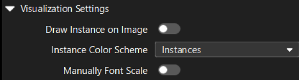
If the Mech-Vision project uses the “Deep Learning Model Package Inference” Step to assist recognition, disable the Draw Instance on Image option in the Visualization Settings to improve the execution speed of the Step.
Disable Debug Output
Debug output is usually used to view and analyze the visualization result or debug information of each Step. Debugging is very useful during the application deployment, but not necessary during normal production operations.
Disabling debug output can reduce the extra computation burden and memory usage, thus increasing the speed of vision processing.
Improve IPC Performance
The vision processing task requires high computing performance. Selecting IPC with a better performance can greatly improve processing speed and parallel processing capability. In addition, optimizing the performance of the IPC can improve the image acquisition and data transmission speed. Together, these factors can effectively improve the efficiency and responsiveness of vision applications.
Path Planning
| In the Mech-Viz, improper parameter settings can lead to collisions. Make sure to conduct thorough testing when modifying the parameters. |
Improve Time Planning
For EIH scenarios, it is recommended to capture images immediately after the robot picks the workpiece. With this strategy, the robot only needs to stop during image capturing and start placing after image capturing. While the robot places the workpiece, data is processed in the background so that the robot can quickly pick the next workpiece after placing.
|
If the execution time for the robot to place the workpiece is shorter than the time for vision processing and outputting the picking pose, the robot needs to stop and wait. |
For the ETH scenario, it is recommended to capture images after the robot picks the workpiece and moves out of the camera’s FOV. This strategy may not require the robot to stop for image capturing. While the robot moves, data is processed in the background so that the robot can quickly pick the next workpiece after placing.
|
Whether the robot needs to wait depends on which of the following two operations takes longer:
If the robot moves longer, the robot does not need to stop and wait. If the latter takes longer, the robot needs to stop and wait. |
For some carton depalletizing applications, while ensuring that the positions of other cartons do not change after each pick, you can use the “Capturing a single image to achieve the picking of multiple objects” solution. That is, the Mech-Vision can recognize multiple objects at a time and provide all their poses, and the robot can pick all recognized cartons in batches. This significantly saves the time for image capturing. In addition, if the gripper is large enough, you can also consider picking multiple boxes at once to further improve picking efficiency.
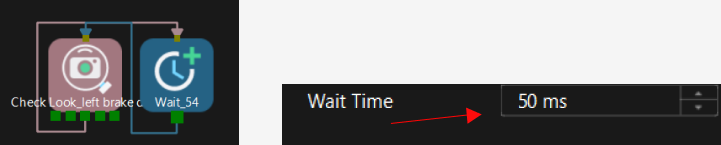
For scenarios where picking is repeated, it is recommended to reduce the wait time to obtain the vision result. It is often recommended to limit the wait time to less than 50 ms to ensure that the system can respond quickly and run efficiently.
Improve the Gripper and Signal Planning
The recommendations for improving the gripper and signal planning are as follows:
-
Reduce the wait time after the gripper is opened and closed.
A short period of waiting time may result in failure to pick and unstable placement. Please make sure to conduct thorough testing before modifying to verify the stability of picking and placing. -
Open the vacuum gripper beforehand.
Ensure that the suction cup is fully ventilated beforehand, which can improve the cycle time during picking and avoid the impact of exposure to other workpieces.
-
Modify the gripper switch signal during movement.
Modifying the gripper switch signal dynamically when the robot moves can smooth the movement and reduce jamming, thus optimizing the overall cycle time of the project.
-
Simplify the gripper model.
Optimizing the gripper model to remove unnecessary parts for collision detection can significantly reduce the time of the Mech-Viz spent on collision calculation. Simplifying the model can speed up the calculation and improve the overall system response efficiency.
Improve Scene Planning
The recommendations for improving scene planning are as follows:
-
Simplify the scene model.
Consider simplifying complex scene models without compromising the accuracy of collision detection. By reducing complex geometric solids or unimportant details in the scene, you can significantly reduce the time of the Mech-Viz spent on collision calculation.
-
Replace dynamic bins with fixed bins.
Using a fixed bin can avoid the frequent need to update the bin’s position. This method applies to scenarios where the loading position remains relatively unchanged. By using a fixed bin, you can reduce the robot’s response time to scene changes during path planning, thus shortening the planning time and improving execution efficiency.
Make sure the loading positions are consistent when using this optimization method.
Improve Path Planning
The recommendations for improving path planning are as follows:
-
Set the intermediate waypoint properly.
Make sure that the intermediate point is as close to the picking point and placing point as possible, and minimize unnecessary intermediate points. Optimizing the position of the intermediate point can reduce unnecessary movement of the robot during picking and placing, thus improving the efficiency of path planning and the overall cycle time.
-
Reduce the rotation of the 6th axis of the robot.
For some robots, the 6th axis rotates slowly, so efforts should be made to minimize these motions during path planning. By properly designing the symmetry of the gripper and the placing position of the workpiece, reliance on the 6th axis can be reduced, thus improving the robot’s operation speed and cycle time.
-
Increase the blend radius of the intermediate point.
Increasing the blend radius can create a smoother and more continuous path for robot movement when setting the intermediate point. A smooth path reduces the acceleration and deceleration time of the robot, thus improving the overall move speed and path planning efficiency.
-
Decrease the Z-axis lifting height.
Reduce the lifting height of the robot’s Z-axis after picking as much as possible without affecting path planning and safety. Reducing the lifting height can shorten the relative move distance of the robot, thus reducing the move time and improving cycle time.
Enable Operator Mode
In the Mech-Viz toolbar, click the Operator Mode option to enable the operator mode.
After the operator mode is enabled, the software will block certain collision detection features, including “Skip remaining calculation of this solution if collision degree exceeds threshold” and “Do not store in plan history”. In addition, the software reduces the point cloud display density, thus improving the execution speed of the software.
Robot Picking and Placing
The absolute accuracy of the robot must be ensured during picking and placing. Maintainers should conduct regular checks on the robot.
-
Check if the robot base is shaking. If so, you must stop using the robot and re-secure the base.
-
Check if the zero position of the robot is offset. A zero position offset may affect the robot’s accuracy. For more guidance on checking the absolute accuracy of the robot, please refer to Check the Robot Absolute Accuracy.