Generate and Edit Matching Templates in Mech-MSR
In Mech-MSR, use the 2D template editor to define 2D regions of interest (ROIs) on the image. Data within the ROI is used to extract edge features for generating a 2D matching template.
The extracted edge features should meet the following requirements:
-
Common to all images: If the extracted edge features are not present in all images, matching between the images and the template may fail.
-
Representative: Extracted edge features must be representative to ensure unique and accurate matching; otherwise, matching results may be incorrect.
-
Moderate quantity: In general, more extracted edge features improve matching accuracy. However, an excessive number may reduce matching speed.
Start the Feature
In the parameter configuration panel of the Step, click the Open the editor button to open the 2D Template Editor.
-
2D Scenarios: 2D Alignment, 2D Matching
-
3D Scenarios: Surface Alignment, Surface Matching
| Matching templates cannot be used across scenarios. |
Preparations
-
Ensure that the Step has proper input.
-
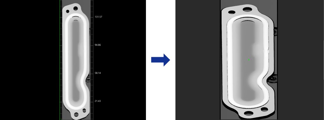
Under Parameters in the parameter configuration panel of the Step, click the Open the editor button to open the 2D Template Editor. This tool will automatically obtain the input image of the Step.
|
Workflow
-
Rename the default template or click the + New button to create a new template.
After selecting a template from the template list, right-click and select the Rename option, enter a custom name, and click the OK button to rename the template. 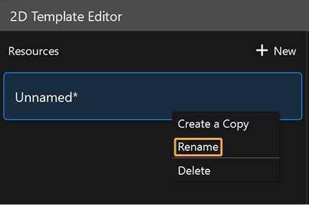
-
Select an ROI. Ensure that the edge features in the ROI are representative and not excessive.
Instruction: Click the icon on the toolbar to the right of the template list to select the appropriate ROI tool and create ROIs in the image. Note that the extracted edge features will only take effect when a feature region or ROI is used in the Step. Otherwise, the generated matching template will lead to matching failure.
-
In the ROI list section at the bottom left of the interface, right-click an ROI and select Enable, Disable, etc., to set the drawn ROI.
-
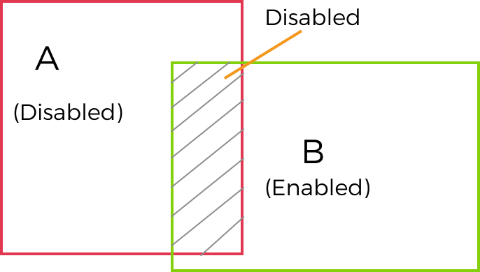
For overlapping areas, Disable has priority over Enable. In other words, when one region is set to Enabled and an overlapping region to Disabled, the overlapping area is effectively Disabled; edge features within it are ignored and not used for template generation.
-
-
Set the template coordinate system. Click Edit origin to set the coordinate system origin, and adjust Angle as needed to set the coordinate system direction.
-
Set Feature parameters.
-
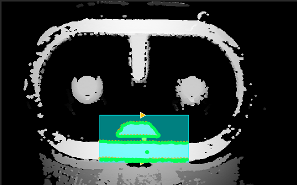
Click the Generate template button in the lower-right corner to generate and preview the template.
-
Click the Save button in the lower-right corner to save the generated template.
If you only clicked the Save button in the lower-right corner and did not generate a template, the edited template would be saved but would not work.
After configuration, close the editor. Click ▼ under the Open the editor button in the Step and then select the corresponding template in the drop-down menu.
ROI Drawing Tools
The usage instructions on ROI drawing tools are shown in the table below.
| Icon | Tool | Instructions |
|---|---|---|

|
Circle ROI Tool |
Use the Circle ROI Tool to draw a circular ROI.
|

|
Rectangle ROI Tool |
Use the Rectangle ROI Tool to draw a rectangular ROI.
|

|
Polygon ROI Tool |
Use the Polygon ROI Tool to draw a polygonal ROI.
|

|
ROI Eraser Tool |
Use the ROI Eraser Tool to erase the drawn ROI, and the points in the erased parts will not be used to generate the template.
|

|
Select Tool |
Use the Select Tool to select and edit the drawn ROI.
|


|
Set the Template Coordinate System
Origin X, Origin Y, and Angle jointly define the template coordinate system:
-
Origin X and Origin Y: Define the position of the template coordinate system origin in the current image.
-
Angle: Defines the direction of the template coordinate system, that is, the angle between the positive X-axis of the template coordinate system and that of the image coordinate system. Clockwise is positive, and counterclockwise is negative.
The template coordinate system is saved with the template. The 2D Matching, 2D Alignment, Surface Matching, and Surface Alignment Steps output Object Pose based on the template coordinate system. When Object Pose is input to downstream Steps, these Steps can adjust their ROIs or feature regions according to the pose changes of the target objects.
Setting Method
Set the template coordinate system as follows:
-
In the Set template coordinate system section, click Edit origin.
-
In the drawing area, select an easily identifiable feature point with a stable position, such as the center of a circular hole, and click it to set the template coordinate system origin. Alternatively, set Origin X and Origin Y to specify the origin position precisely.
-
Adjust Angle to set the positive X-axis direction of the template coordinate system.
-
Click Generate template, and then click Save.
| After changing the template coordinate system, you do not need to regenerate the template, but you must save it again. Otherwise, the new template coordinate system will not take effect. |
Applicable Scenarios
When creating a template for the first time, you must click Edit origin to establish the template coordinate system. To adjust the coordinate system direction, set Angle to define the positive X-axis direction.
For a project in which the positioning or measurement process has already been configured, you may need to recreate a template for the same target object while continuing to use the existing ROIs or feature regions in downstream Steps. In this case, ensure that the object has the same imaging scale in the new and original templates, and configure the new template based on the original template as follows:
-
Set the coordinate system origin of the new template at the same feature position on the object.
-
Make the X-axes of the new and original templates point in the same direction relative to the object.
| When setting the coordinate system of the new template, you do not need to calculate the angle difference between the new and original templates based on the angle of the original template. With the object as the reference, simply keep the origins and X-axis directions of the two template coordinate systems consistent. |
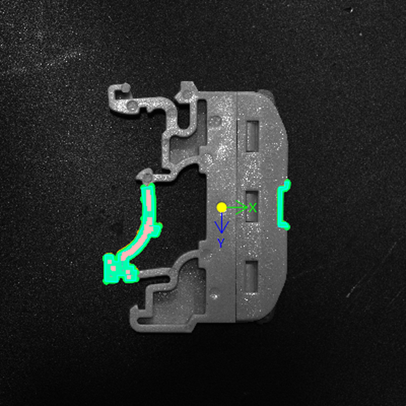
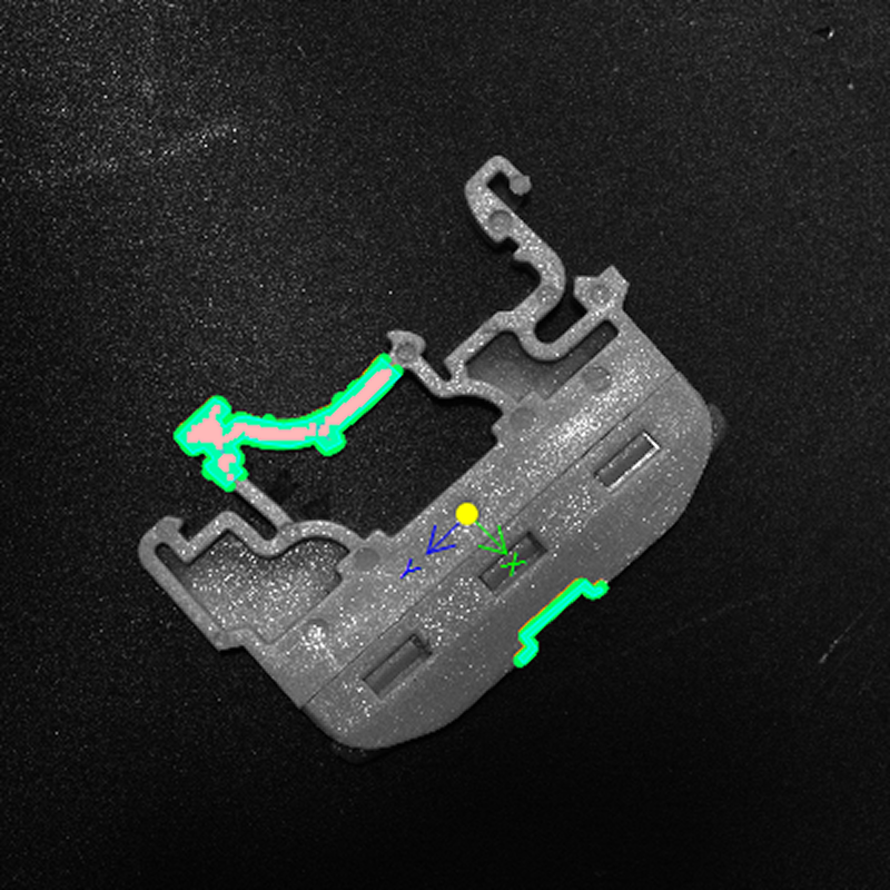
As shown below, the object has different angles in the original and new templates. The origins of both templates' coordinate systems are located at the same circular feature on the target object, with both X-axes pointing from this feature toward the curved outer edge. Therefore, the two template coordinate systems have the same position and direction relative to the target object.
|
|
Original template |
New template |
After switching to the new template, the existing ROIs or feature regions in downstream Steps still cover the original target areas on the object and do not need to be adjusted again.
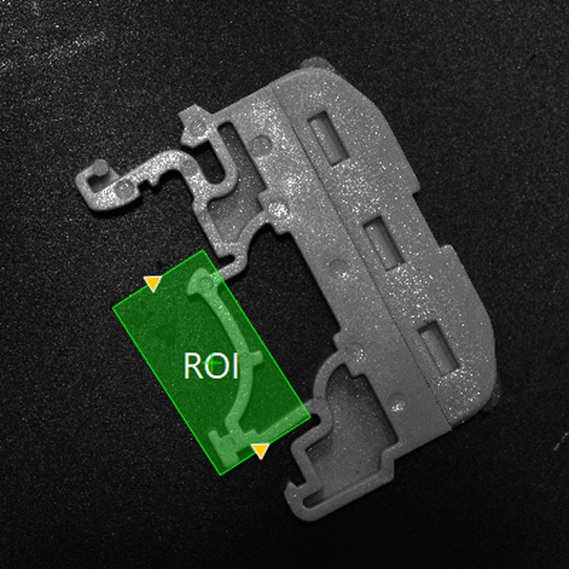
| This effect applies only when downstream Steps use Object Pose to adjust their ROIs or feature regions. When Alignment Parameter Group is used, adjustment is still required after switching templates. |
Feature Parameters
| Parameter | Description |
|---|---|
Search scale |
The downsampling scale applied to the template image during the fast search phase. Higher scales increase search speed at the cost of feature resolution. In the Auto Mode, the system will select the optimal search scale based on the image content. |
Search step |
The search step size, at the subpixel level, during fine matching. A smaller step improves search accuracy but increases computation. |
Edge Threshold |
Points with a gradient magnitude greater than or equal to this value are considered edge features and used for template matching. |
Min chain length |
The minimum number of feature points required for an edge contour. Contours with fewer points are removed to filter out noise. |
|
After confirming that the edge features in the ROI are stable and representative, you can quickly adjust the feature parameters along the following steps:
It is recommended to adjust only one parameter at a time and observe the result after regenerating the template. |