Geometric Features and Feature Points
Read the following to learn about the geometric features and feature point types.
Geometric Features
Feature regions are often used in Mech-MSR to determine certain features of a surface or profile. Measurement and detection tasks are performed based on these features. These features are called geometric features.
Geometric features are divided into the following categories:
-
Point: A 2D or 3D point, used for point-to-point or point-to-line measurement.
-
Line: A straight line that is infinitely long, used to determine the orientation, or to intersect with another line to generate a feature point for measurement.
-
Plane: A plane fitted to the surface data, used for point-to-plane or line-plane intersection measurements.
-
Circle: A circle fitted by surface or profile data.
Geometric features are usually taken as inputs by measurement-related Steps.
See also
Feature Points
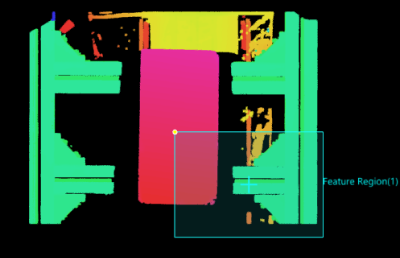
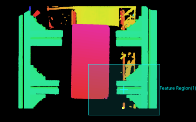
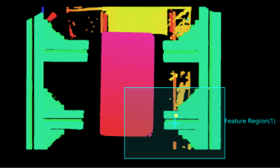
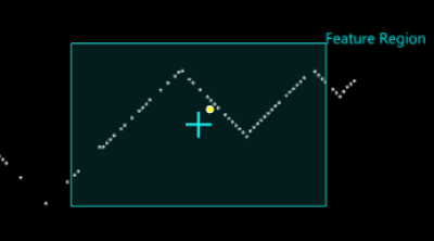
In Mech-MSR, feature points in a defined region are often used for dimensional and positional measurements. Generally, feature points are obtained from the profile or surface data and represent a specific position that is processed by a specific Step to complete the measurement task.
The following types of points can be identified in a measurement region. The availability of a feature point type is Step-dependent.
| Feature Point Type | Description | Illustration | ||
|---|---|---|---|---|
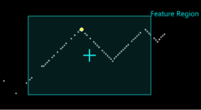
Max Z |
The point with the maximum Z value in the region of interest. |
|
||
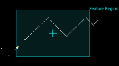
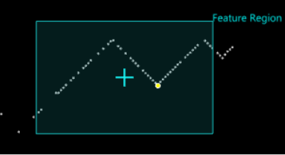
Min Z |
The point with the minimum Z value in the region of interest. |
|
||
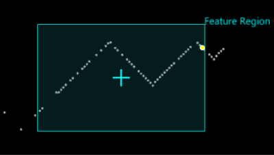
Max X |
The point with the maximum X value in the region of interest. |
|
||
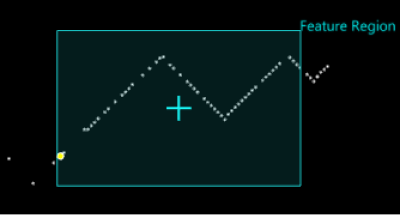
Min X |
The point with the minimum X value in the region of interest. |
|
||
Max Y |
The point with the maximum Y value in the region of interest. |
|
||
Min Y |
The point with the minimum Y value in the region of interest. |
|
||
Centroid |
The center of gravity of the solid shapes formed by the surface data in the region and the Z = 0 plane. |
|
||
Average |
The average location of points in the region of interest. |
|
||
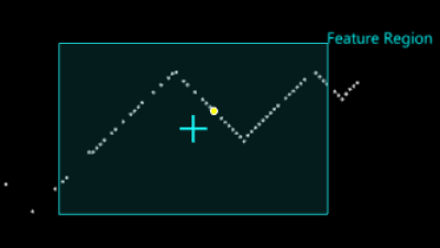
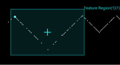
Corner |
A corner of a profile in the region of interest, where corner is defined as a change in profile shape. When there are multiple corners, the point with the most significant change in profile shape is output. |
|
||
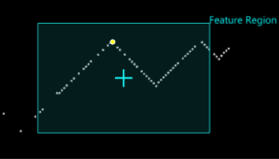
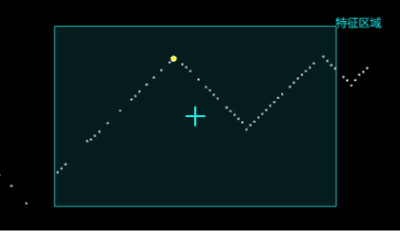
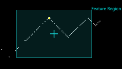
Top corner |
The top-most corner in the region of interest, where corner is defined as a change in profile shape. |
|
||
Bottom corner |
The bottom-most corner in the region of interest, where corner is defined as a change in profile shape. |
|
||
Left corner |
The left-most corner in the region of interest, where corner is defined as a change in profile shape. |
|
||
Right corner |
The right-most corner in the region of interest, where corner is defined as a change in profile shape. |
|
||
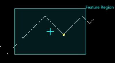
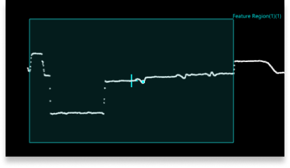
Rising edge |
A rising edge in the region of interest, and the feature points are not necessarily points on the profile. |
|
||
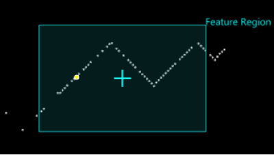
Falling edge |
A falling edge in the region of interest, and the feature points are not necessarily points on the profile. |
|
||
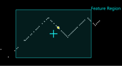
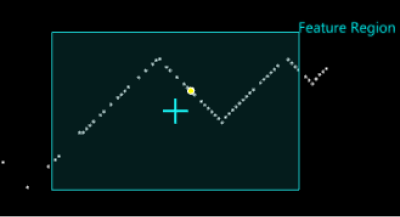
Any edge |
A rising or falling edge in the region of interest, and the feature points are not necessarily points on the profile. |
|
||
Median |
The median location of points in the region of interest. |
|
||
Inflection Point |
The concave up and concave down points respectively of the convex and concave shapes on the profile in the region of interest.
|
|
||
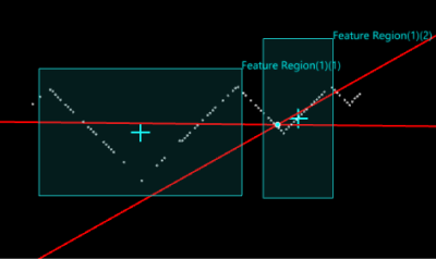
Intersection |
Set Feature Region 1 and Feature Region 2 separately to fit two lines, and the intersection of the two lines is the feature point. |
|
||
Contact |
Set Feature Region 1 to fit a line, and set Feature Region 2 to fit a circle. Create a perpendicular line to the fitted line through the center of the fitted circle, and the foot of the perpendicular line is the feature point.
|
|
||
Percentile |
Setting Low Percentile and High Percentile excludes points below the low percentile or above the high percentile in the region of interest. Feature points are obtained by averaging the remaining points. |
|
See also
