Vision System Hardware Setup
Vision system hardware setup refers to integrating the hardware (camera and industrial PC) into the actual environment to support the normal operation of the vision system.
In this phase, you need to install and connect the hardware of the vision system.
Follow the steps below to build the Mech-Mind Vision System: Check the contents of the package → Install the hardware → Connect the network → Upgrade the software (optional) → Confirm that the vision system can capture images normally.
| If the project requires a high picking accuracy, ensure a good picking accuracy of the application during deployment according to the guidance in Topic: Improving Picking Accuracy. |
Check the Contents of the Package
-
Make sure that the package is intact when you receive it.
-
Check the contents against the “packing list” in the package to ensure that no devices or accessories are missing or damaged.
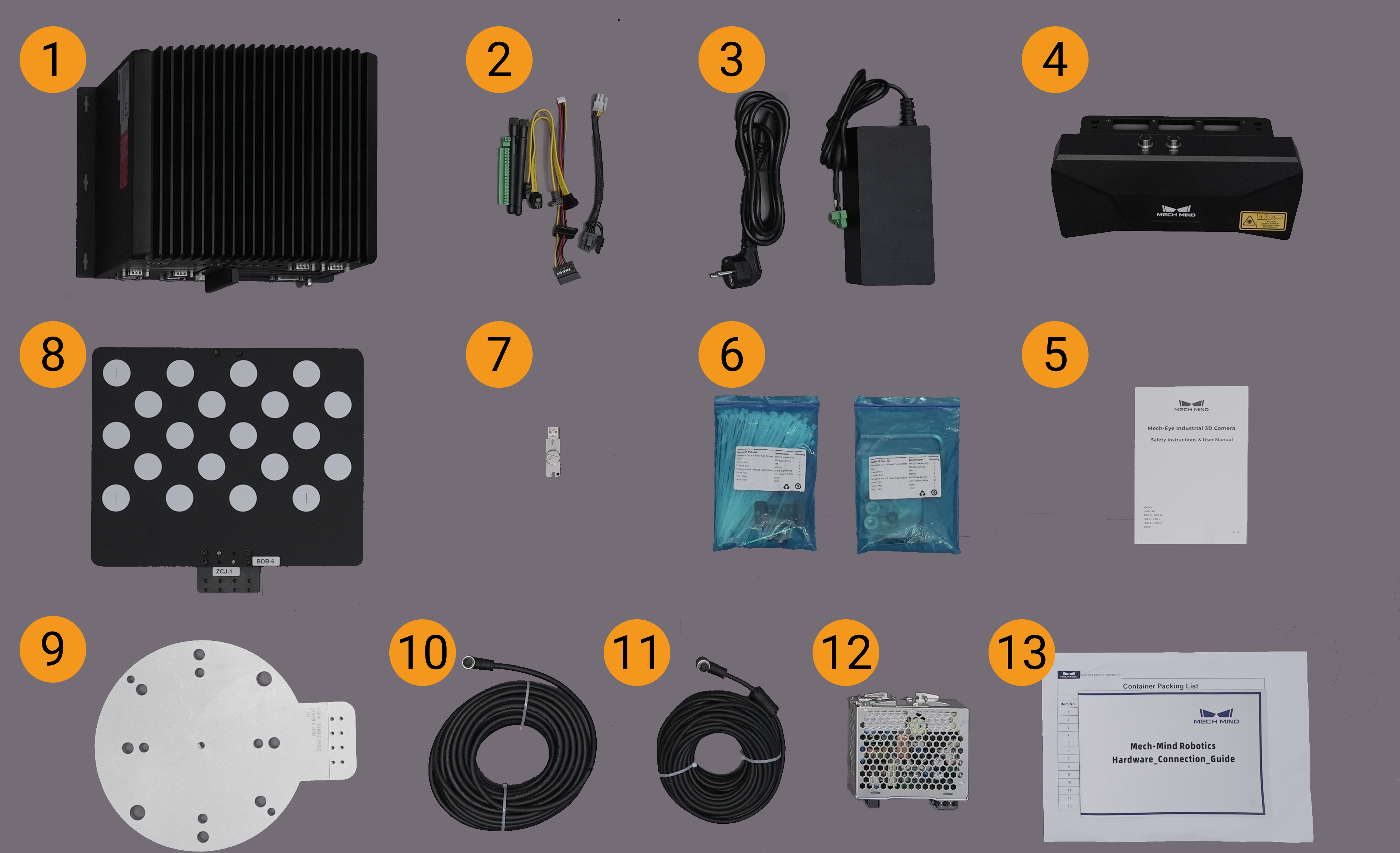
The following figure shows the devices and accessories included in a vision system shipment. The table below is for reference only. Please take the “packing list” in the package as final.
| No. | Category | Name | Function |
|---|---|---|---|
1 |
IPC and accessories |
IPC |
Provides running environment for Mech-Mind software |
2 |
IPC accessories |
Provides IPC accessories, such as antennas for WIFI connection |
|
3 |
IPC power cable and adapter |
Supplies power to IPC |
|
4 |
Camera and accessories |
Mech-Eye Industrial 3D Camera |
Captures images |
5 |
User manual |
Mech-Eye Industrial 3D Camera User Manuals |
|
6 |
Camera accessory box |
Mounts the camera |
|
7 |
Project accessories |
License dongle |
Authorizes the Software Suite license |
8 |
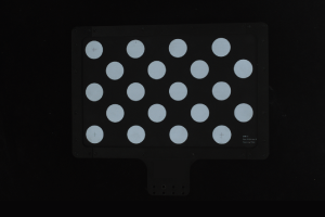
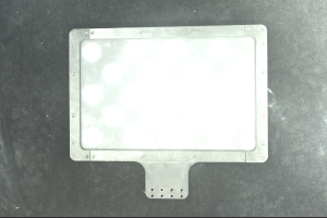
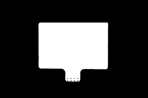
Calibration board |
Calibrates the camera |
|
9 |
Flange adapter |
Connects the calibration board to the robot flange |
|
10 |
Camera DC power cable (standard: 20 meters) |
Connects the camera and the DIN rail power supply; Longer power cables are an option |
|
11 |
Camera Ethernet cable (standard: 20 meters) |
Connects the camera and the IPC; longer camera Ethernet cables are an option |
|
12 |
DIN rail power supply (standard) |
Supplies power to Mech-Eye Industrial 3D Camera; The camera power adaptor is an option |
|
13 |
Packing list |
Lists all the devices and accessories in the package |
|
|
Contact Mech-Mind if any items are missing or damaged. |
Prepare Other Materials
In this tutorial, besides the items in the package, you still need to prepare the materials shown in the following table by yourself.
| Item | Function |
|---|---|
Monitor |
Provides display for the IPC |
HDMI cable |
Connects the monitor and the IPC |
RJ45 Ethernet cable |
Connects the IPC and the robot controller |
| The IPC and robot controller usually are directly connected through an RJ45-to-RJ45 Ethernet cable, and the IPC and the camera are directly connected through the camera Ethernet cable. Alternatively, you can use a router to connect the IPC and the robot controller, and the IPC and the camera, which is not covered in this topic. |
Install Hardware
| If the selected camera mounting mode is eye to hand (ETH) in the vision solution design stage, please follow the section Mount Camera (ETH); if the selected mounting mode is eye in hand (EIH), please follow the section Mount Camera (EIH). |
Mount Camera (ETH)
| In the ETH mode, the camera is fixed on a stand independent of the robot. |
Mount the camera mounting brackets according to the section Camera Bracket Design and Mounting in ETH Setup. After the camera bracket is mounted securely, you can start to mount the camera.
-
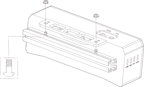
Get the camera mounting bolts and wrench from the camera accessory box.
-
Tighten the two bolts with the wrench as shown below.
-
Please remove the lens protection film after mounting the camera.
-
Power the camera with the DIN rail power supply.
-
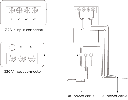
Connect the DC power cable:
-
Connect the +V wire to the +V connectors of the 24 V output connectors;
-
Connect the -V wire to the -V connectors of the 24 V output connectors;
-
Connect the PE wire to the 220 V input connector
 .
.
-
-
-
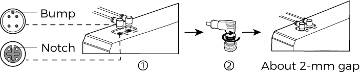
Install the Ethernet cable of the camera.
Make sure the bump of the M12 connector and the notch of the ETH port, and tighten the nut after plugging in the cable.
-
Secure, wire, and route the camera Ethernet cables and power cables according to the section Guidelines for Mounting Camera Cables.
Mount Camera (EIH)
| In the EIH mode, the camera is mounted on the last joint of the robot through a camera mounting bracket. |
Mount the camera mounting brackets according to the section Camera Bracket Design and Mounting in EIH Setup. After the camera bracket is mounted securely, you can start to mount the camera.
-
Get the camera mounting bolts and wrench from the camera accessory box.
-
Tighten the two bolts with the wrench as shown below.
-
Please remove the lens protection film after mounting the camera.
-
Power the camera with the DIN rail power supply.
-
Connect the DC power cable:
-
Connect the +V wire to the +V connectors of the 24 V output connectors;
-
Connect the -V wire to the -V connectors of the 24 V output connectors;
-
Connect the PE wire to the 220 V input connector
.
-
-
-
Install the Ethernet cable of the camera.
Make sure the bump of the M12 connector and the notch of the ETH port, and tighten the nut after plugging in the cable.
-
Secure, wire, and route the camera Ethernet cables and power cables according to the section Guidelines for Mounting Camera Cables.
Mount the IPC
|
The IPC is normally mounted in the control cabinet of the robot. The environment in which the IPC is mounted requires good heat dissipation, ventilation, and dust protection. It should be mounted at a location where Ethernet cables, HDMI cables, and USB ports can be easily mounted and maintained. |
To mount the IPC, follow these steps:
-
Prepare the wrench, bolts, nuts, and gaskets that are not included in the package beforehand.
-
If the robot controller is designed with mounting holes for the IPC in it, secure the IPC in the controller: place the bolt, gasket, and nut one by one, and tighten the two bolts with a wrench, as shown below.
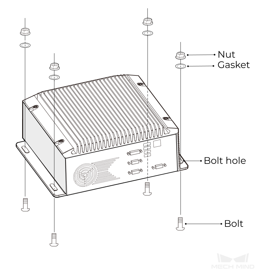
If the location of the robot controller is already fixed, skip this step and just place the IPC inside the controller.
-
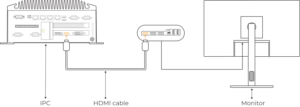
Connect the IPC and the monitor with the HDMI cable.
Plug one end of the HDMI cable into the HDMI port of the monitor, and the other end into the HDMI port of the IPC, as shown below.
-
Connect the IPC to the power supply unit with the power adaptor.
Plug the power cable of the power adaptor into the power connector of the IPC. Connect the adaptor to the power supply on the other end.
-
Insert the license dongle.
Plug the license dongle into a USB port of the IPC.
-
After the IPC is connected to the power supply, switch on the IPC.
-
If the IPC is started normally, the power indicator should be solid on.
-
If the IPC cannot be started, contact Mech-Mind Technical Support.
-
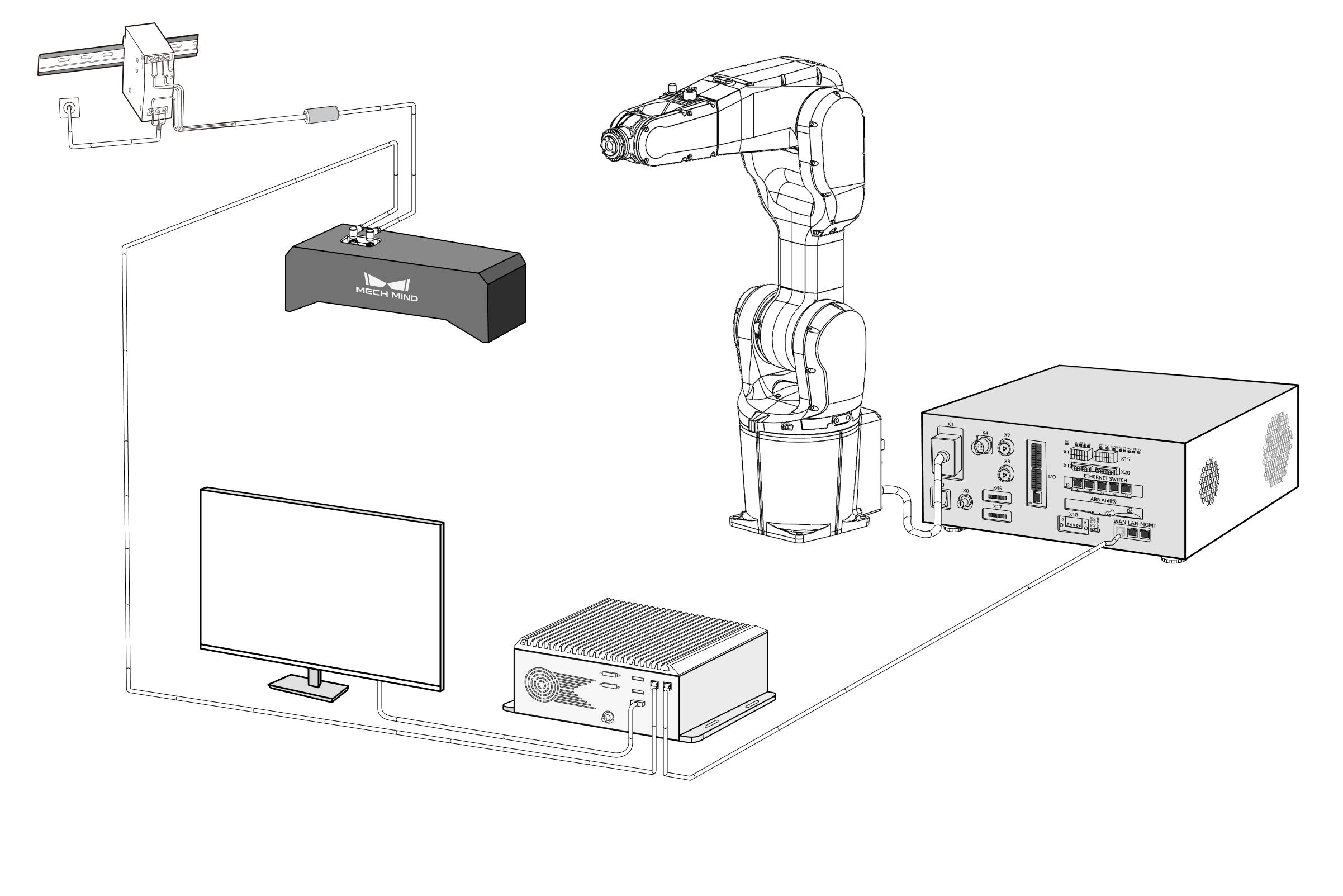
Connect the Network
In this section, you will learn how to connect the network between the IPC and the camera, and between the IPC and the robot.
In the following sections, the following IP addresses will be used for network settings. Please adjust the network settings according to your actual network environment.
| Device | IP Address | |
|---|---|---|
IPC |
Ethernet port connecting to the camera |
192.168.100.10 |
Ethernet port connecting to the robot controller |
192.168.200.10 |
|
Camera |
192.168.100.20 |
|
Robot |
192.168.200.20 (already set on the robot) |
|
Connect the IPC and the Camera, and the IPC and the Robot Controller
-
Plug the other end of the Ethernet cable connected to the camera into an Ethernet port of the IPC.
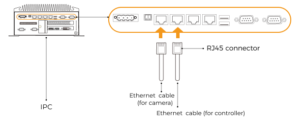
-
Use an RJ45-to-RJ45 Ethernet cable to plug one end into the Ethernet port of the robot controller and the other end into an Ethernet port of the IPC.
Set the IP Addresses on the IPC
-
Select on the IPC. The Network Connections page will be displayed.
-
Right-click the Ethernet port connected to the camera, and select Rename to rename the Ethernet port, such as “To_camera”.
-
Right-click the Ethernet port connected to the camera, and select Properties to enter the Ethernet Properties page.
-
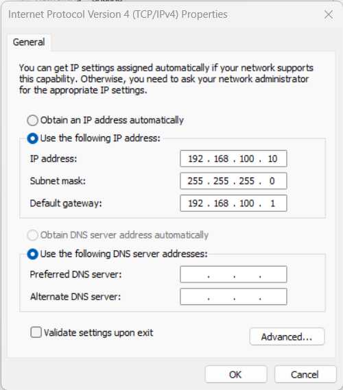
Select the Internet Protocol Version 4 (TCP/IPv4) checkbox, and then click the Property button to enter the Internet Protocol Version 4 (TCP/IPv4) Properties page.
-
Select the Use the following IP address radio button, set the IP address to “192.168.100.10”, Subnet mask to “255.255.255.0”, and Default gateway to “192.168.100.1”, and then click the OK button.
-
Repeat steps 2 to 5 to rename the Ethernet port connected to the robot controller (for example, “To_robot”), and set the IP address for this Ethernet port. For example, the IP address of this Ethernet port is “192.168.200.10”.
The IP address of the robot and that of the IPC Ethernet port connected to the robot controller must be on the same subnet.
Set the Camera IP Address
-
Double-click
 on the IPC to open and run Mech-Eye Viewer.
 -
Select the camera in the camera list, and hover the cursor on the camera. Click
 to open the Config Camera Network dialog box.
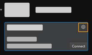
If the camera cannot be found or connected, please refer to Camera Troubleshooting.
-
In the Camera area, select the Set as Static IP radio button, set IP Address Class to “Class C 192.168.x.x”, IP Address to 192.168.100.20, and Subnet Mask to “255.255.255.0” and then click Apply.
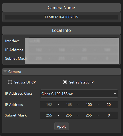
|
The IP address of the camera and that of the IPC Ethernet port connected to the camera must be on the same subnet. |
Test the Network Connectivity
-
Press Win + R to open the Run dialog box.
-
Type
cmdin the Run dialog box, and then click OK. -
Type ping XXX.XXX.XX.XX in the command prompt window and press Enter to execute the command.
Replace XXX.XXX.XX.XX with the actual IP address of the camera/robot.
If the network connectivity is normal, you should receive the following response:
Pinging XXX.XXX.XX.XX with 32 bytes of data:
Reply from XXX.XXX.XX.XX: bytes=32 time<1ms TTL=128
Reply from XXX.XXX.XX.XX: bytes=32 time<1ms TTL=128
Reply from XXX.XXX.XX.XX: bytes=32 time<1ms TTL=128
Reply from XXX.XXX.XX.XX: bytes=32 time<1ms TTL=128
Confirm the Quality of Captured Images
After testing the network connectivity between the IPC and the camera/robot, please confirm that the vision system can capture images normally and confirm that the captured images meet quality standards:
-
Place workpieces at the center of the camera’s field of view (FOV), and make sure that the workpieces on the edge and top are all within the FOV.
-
Open and start Mech-Eye Viewer by double-clicking
on the IPC. -
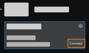
Select the camera in the camera list and click Connect.
-
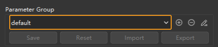
After the camera is connected, select the parameter group according to the actual requirement.
Starting from firmware 2.2.0, built-in parameter groups suitable for different scenarios or target objects are added to V4 cameras. After selecting the parameter group that corresponds to your actual situation, you only need to adjust the parameter values slightly to acquire satisfactory data, simplifying the process of parameter adjustment. For details, refer to Built-in Parameter Groups.
-
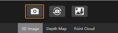
After selecting a parameter group, click the Capture once button.
-
Make sure that the captured images meet the following standards.
-
2D image: The captured 2D image is not significantly overexposed (too white to recognize objects) or underexposed (too dark to recognize object details).
-
Depth map and point cloud: All relevant parts of the object can be recognized.
Normal Overexposed Underexposed 2D image
Point cloud
-
|