Calibration Board
Calibration board is usually used for intrinsic parameter check and hand-eye calibration. This article introduces the types, models, and mounting methods of calibration boards.
|
If you need the installation drawings and 3D models of calibration boards, click here to download them. |
Calibration Board Types and Models
Mech-Mind provides two types of calibration boards: CGB and OCB.
CGB
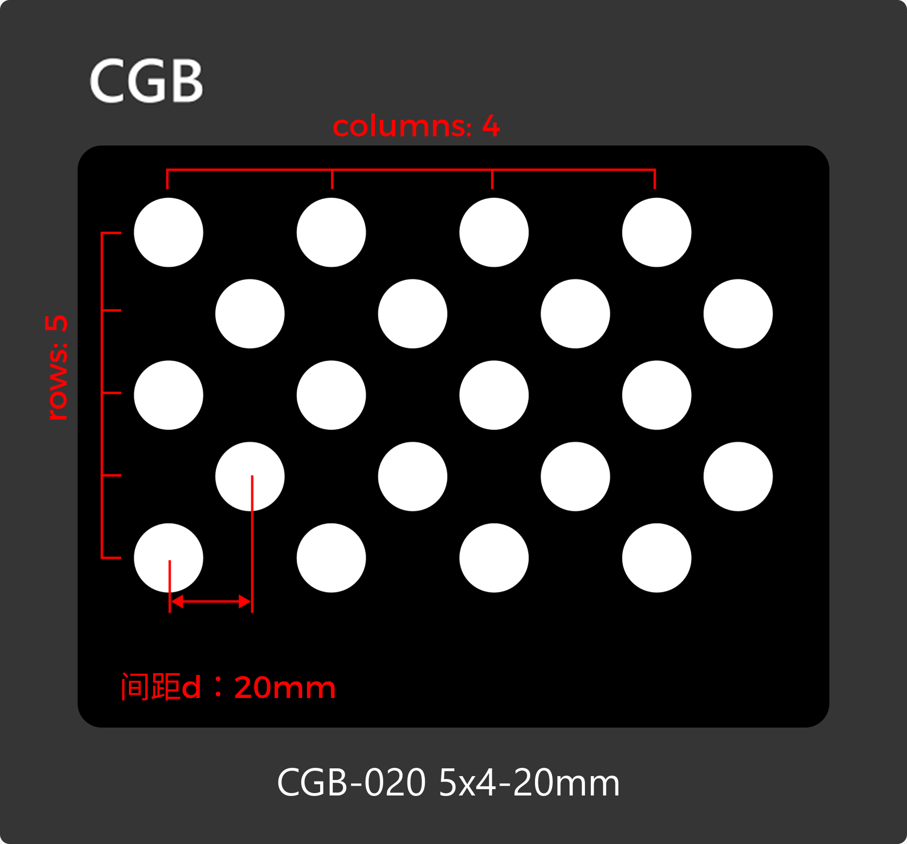
The following figure shows a CGB-type calibration board (CGB-020 as an example).
|
| Model | Material | d (mm) | Rows | Columns | Dimensions (mm) |
|---|---|---|---|---|---|
CGB-020 |
Carbon fiber |
20 |
5 |
4 |
185 x 145 x 2 |
CGB-035 |
35 |
5 |
4 |
303 x 243 x 2 |
|
CGB-050 |
50 |
5 |
4 |
420 x 340 x 3 |
OCB
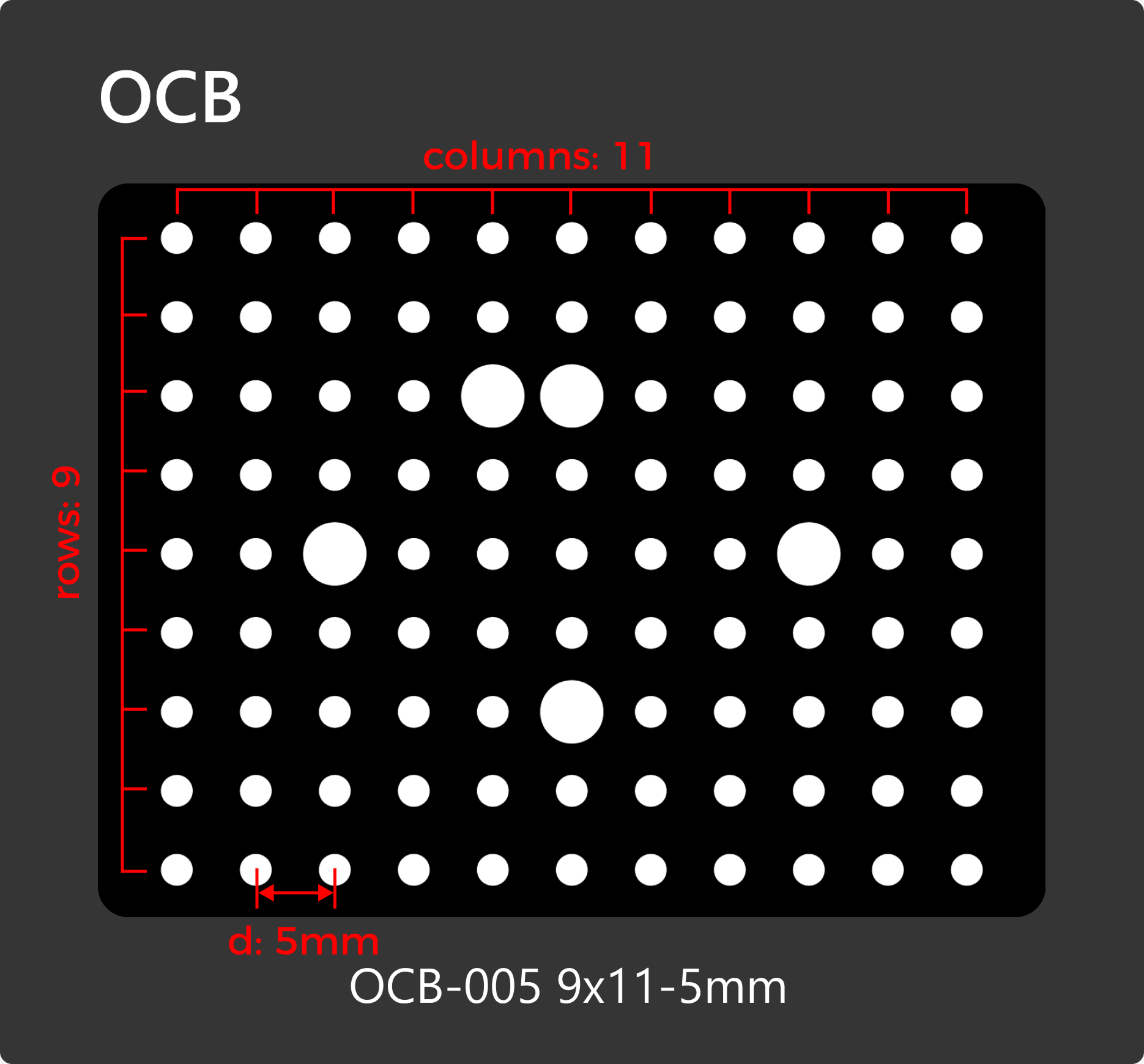
The following figure shows a OCB-type calibration board (OCB-005 as an example).
|
| Model | Material | d (mm) | Rows | Columns | Dimensions (mm) |
|---|---|---|---|---|---|
OCB-005 |
Glass |
5 |
9 |
11 |
60 x 55 x 3 |
OCB-010 |
10 |
9 |
11 |
120 x 110 x 3 |
|
OCB-020 |
20 |
9 |
11 |
240 x 220 x 3 |
Select the Calibration Board Model
3D Camera Calibration
When performing 3D camera calibration, selecting a proper calibration board can improve the accuracy and stability of calibration. In actual projects, select the proper calibration board according to the camera model and the actual working distance.
To determine the camera model, please refer to How to Read Camera Serial Number. If you still cannot determine the camera model, contact Mech-Mind Technical Support.
| Camera model | Working distance (mm) | Recommended model |
|---|---|---|
UHP-140-GL |
300±20 |
OCB-005 |
NANO-GL |
300–600 |
CGB-020 |
NANO ULTRA-GL |
250–500 |
CGB-020 |
PRO S-GL |
500–800 |
CGB-020 |
800–1000 |
CGB-035 |
|
PRO M-GL |
1000–1500 |
CGB-035 |
1500–2000 |
CGB-050 |
|
LSR S-GL |
500–1000 |
CGB-035 |
1000–1500 |
CGB-050 |
|
LSR L-GL |
1200–3000 |
CGB-050 |
DEEP-GL |
1200–3500 |
CGB-050 |
PRO XS-GL |
300–600 |
CGB-020 |
Log S |
500–800 |
CGB-020 |
800–1000 |
CGB-035 |
|
Log M |
1000–1500 |
CGB-035 |
1500–2000 |
CGB-050 |
|
Laser L Enhanced |
1500–3000 |
CGB-050 |
2D Camera Calibration
When performing 2D camera calibration, selecting a proper calibration board can improve the accuracy and stability of calibration. In actual projects, select the proper calibration board according to the 2D camera calibration task and camera field of view. If you still cannot determine the camera model, contact Mech-Mind Technical Support.
-
Determine the 2D camera calibration task type.
Determine whether the calibration task is distortion calibration or hand-eye calibration according to actual requirements.
-
Estimate the calibration board dimensions.
Acquire an image at the target working distance, estimate the calibration board dimensions according to the following requirements, and select a proper calibration board model.
Calibration type Description Illustration Distortion calibration
It is recommended that the calibration board cover as much of the camera field of view as possible, so that distortion parameters can be calculated stably.
If the calibration board cannot fit entirely within the field of view, use a smaller calibration board first.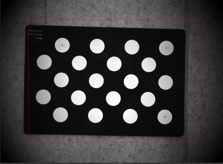
Hand-eye calibration
It is recommended to use the OCB-005 model calibration board.
It is recommended that the calibration board occupy about 1/9 of the field of view in the image (about 8% to 15%), so that feature points can be recognized stably.
If the calibration board is too small and results in insufficient feature points, use a larger calibration board.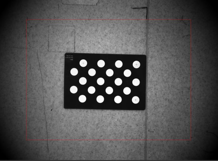
|
Mount the Calibration Board
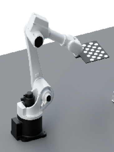
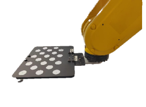
In the following calibration scenarios, you can mount the calibration board on the last joint of the robot.
-
Automatic Calibration in the Eye to Hand (ETH) Scenario
-
Manual Calibration in the ETH Scenario (Multiple Random Calibration Board Poses)
| For other calibration scenarios and intrinsic parameter checks, there is no need to mount the calibration board. Please place the calibration board in the center of the object plane. |
The calibration board can be mounted on the robot end in two ways, as shown below:
| Direct mounting | Mounting through robot flange |
|---|---|
|
|
|
If you use a robot flange to mount the calibration board, you need to purchase a proper model of calibration board from Mech-Mind. For details, refer to Select Robot Model and Robot Flange Model. |