Inspection and Maintenance
On-site equipment needs to be checked according to the inspection standards. Within the specified period, use the correct methods to inspect the camera hardware and software to detect potential faults early and perform timely maintenance and adjustments.
Camera and Accessory Inspection
Camera Enclosure
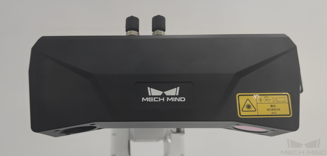
The camera enclosure is a crucial structure that protects the internal precision components and maintains the camera’s sealed condition. It requires regular daily maintenance and care. The recommended inspection frequency is once everyday.
Collision of the camera can be assessed by visually inspecting for any dents, deformations, or scratches on its exterior. If a collision has occurred, you need to check whether the accuracy of the intrinsic and extrinsic parameters have changed using the software. If so, you should stop using it to ensure safety, and the camera should be replaced or the extrinsic parameters should be re-calibrated as soon as possible. (For specific procedures on checking intrinsic and extrinsic parameters, please refer to the “Camera Intrinsic and Extrinsic Parameter Inspection” section.)
Camera Cables
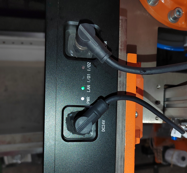
Camera cables include the power cable and the Ethernet cable. The power cable provides the stable voltage required for the 3D camera, while the Ethernet cable ensures a stable data transmission environment for communication between the 3D camera and the IPC. Both need to be inspected regularly as part of daily maintenance. The recommended inspection frequency is once everyday.
It is necessary to regularly check whether cables are aging and the connections at both ends of the camera cables are secure. If the cables run through a robot dresspack, in addition to checking the connections at both ends, you should also check whether the cables show signs of bending, twisting, or wear according to the wear of dresspacks. If any issues are found, please contact Mech-Mind to change cables.
| Disconnect the power supply if the camera will not be used for an extended period of time. |
Camera Mounting Frame
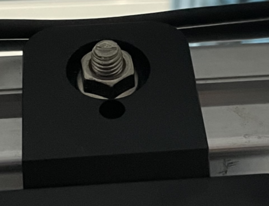
Camera mounting frame is a crucial mounting structure for the 3D camera. The stability of the frame directly affects the accuracy of the 3D camera’s extrinsic parameters, so it needs to be inspected regularly. The recommended inspection frequency is once every two weeks.
You can determine if the camera is securely mounted by visually observing whether the camera mounting frame shows any signs of deformation or movement and whether the connecting bolts are loose. If the inspection fails, you need to check whether the accuracy of the intrinsic and extrinsic parameters have changed using the software. If so, you should stop using it to ensure safety, and the extrinsic parameters should be re-calibrated as soon as possible. (For specific procedures on checking intrinsic and extrinsic parameters, please refer to the “Camera Intrinsic and Extrinsic Parameter Inspection” section.)
IPC and Network Switch Inspection
-
3D vision software is installed on the IPC, and the IPC’s status directly affects the performance and computation time of the vision software. To ensure that the IPC can run smoothly, it is necessary to perform daily inspections regularly. The recommended inspection frequency is once every week.
-
Network switch and Ethernet cables are used for network connections between hardware. Regular inspections can help reduce network communication failures. The recommended inspection frequency is once every week.
-
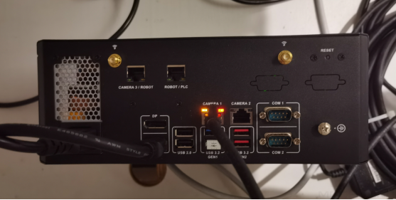
Peripheral devices of the IPC: Key components include the IPC power supply, Ethernet cables, and license dongles; non-key components include keyboard and mouse cables, and HDMI video cables. To ensure stable operation of the IPC, regularly check for any looseness at the cable interfaces. The recommended inspection frequency is once every week.
-
It is recommended to place the IPC in a well-ventilated environment and regularly restart the IPC to ensure that it can run more stably. Ensure that the IPC is not placed in a confined or small space, and avoid placing unrelated items on its surface. The cooling vents of the IPC must remain unobstructed, and there should be at least a 5 cm clearance around the IPC to prevent overheating. The recommended inspection frequency is once every week.
Robot Inspection
The robot is the execution mechanism of the workflow, and its accuracy directly affects picking accuracy.
-
Robot foundation: Check if the robot base is shaking. If so, stop using the robot, re-secure the foundation, and re-calibrate the extrinsic parameters. The recommended inspection frequency is once every six months.
-
Robot zero position: Robot zero-point offset can cause changes in robot accuracy. Please check the zero position by referring to the operation guide of the current robot. If there is a zero-point offset in the robot, stop using it, and re-calibrate the zero position, and the extrinsic parameters. The recommended inspection frequency is once every two months.
Camera Intrinsic and Extrinsic Parameter Inspection
For camera software, primarily check its intrinsic and extrinsic parameters. The two parameters will affect the accuracy of vision recognition. The recommended inspection frequency is once every two months. (Checking the intrinsic and extrinsic parameters of the camera requires using vision software. Please operate under the guidance of a technician.)
|
In addition, please preheat the camera before checking the camera’s intrinsic and extrinsic parameters. The camera cannot effectively guarantee the accuracy of point cloud reconstruction until thermal balance is reached. Please use one of the following methods to warm up the camera:
|
Intrinsic Parameter Check Method
Place the calibration board directly below the camera, ensuring the distance between the board and the camera is as close to the camera’s focal length as possible. The calibration board should be as parallel as possible to the underside of the camera, and then proceed with the software operations.
-
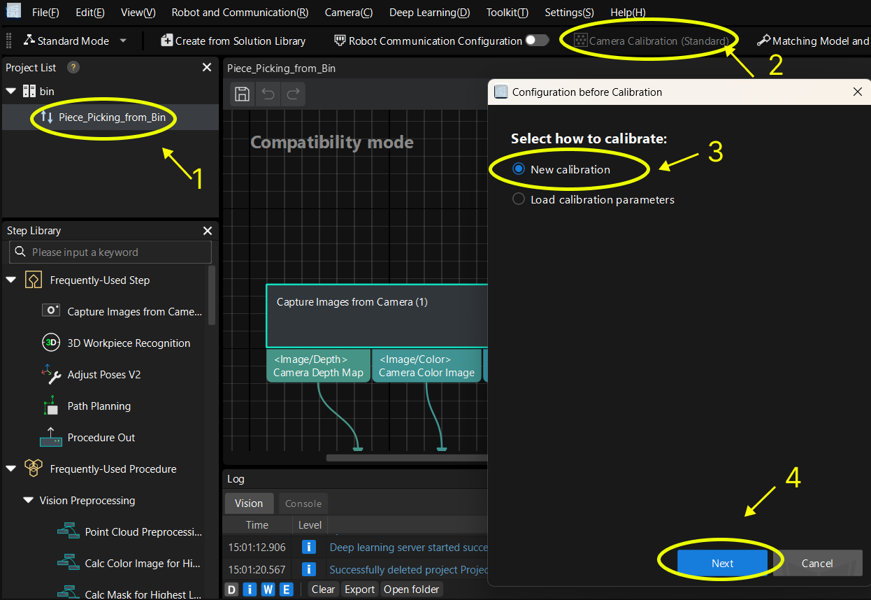
Open the Mech-Vision software, select the project, click the Camera Calibration button, select New calibration, and then click the Next button.
-
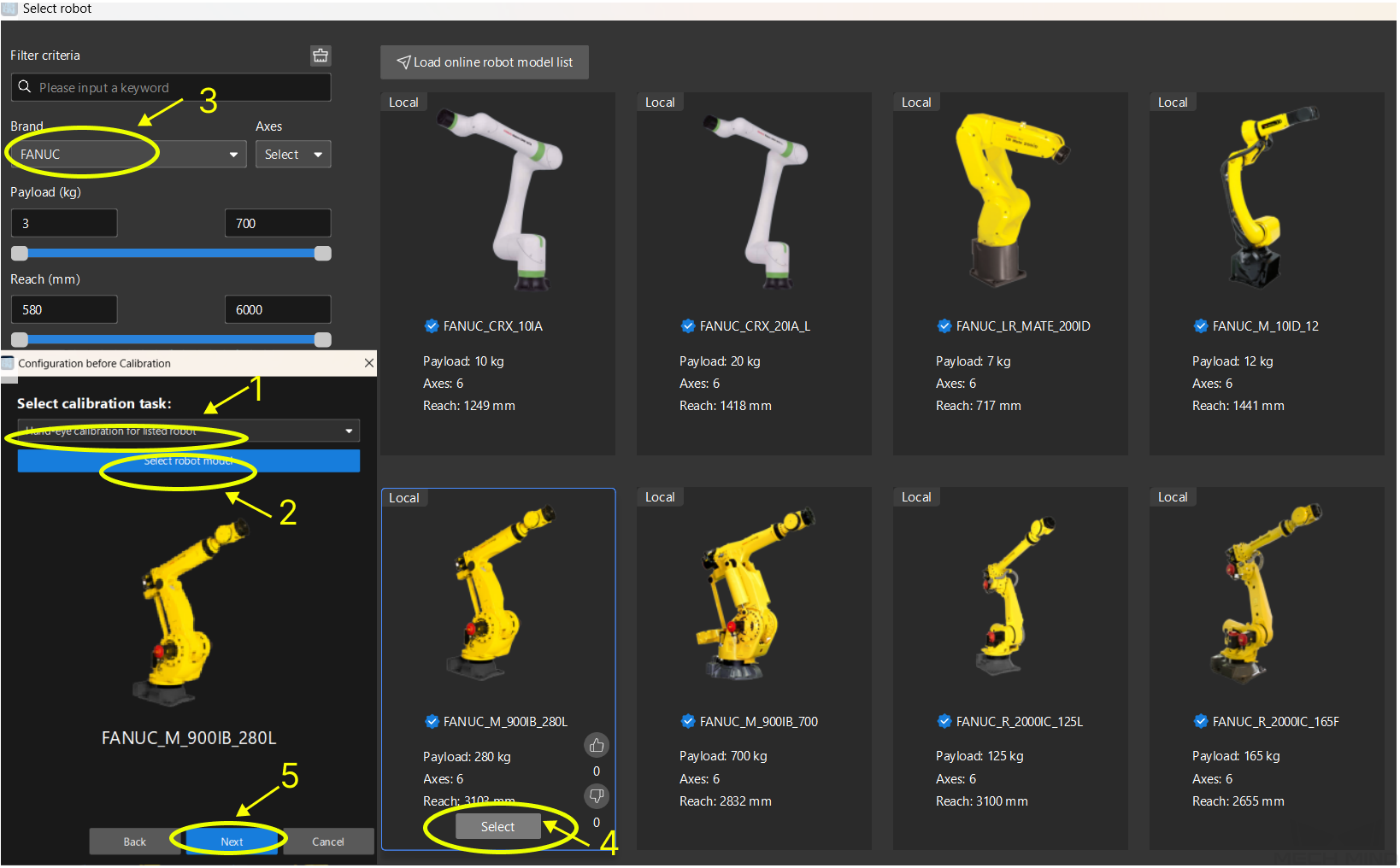
Select the robot model based on the site conditions and then click the corresponding button.
-
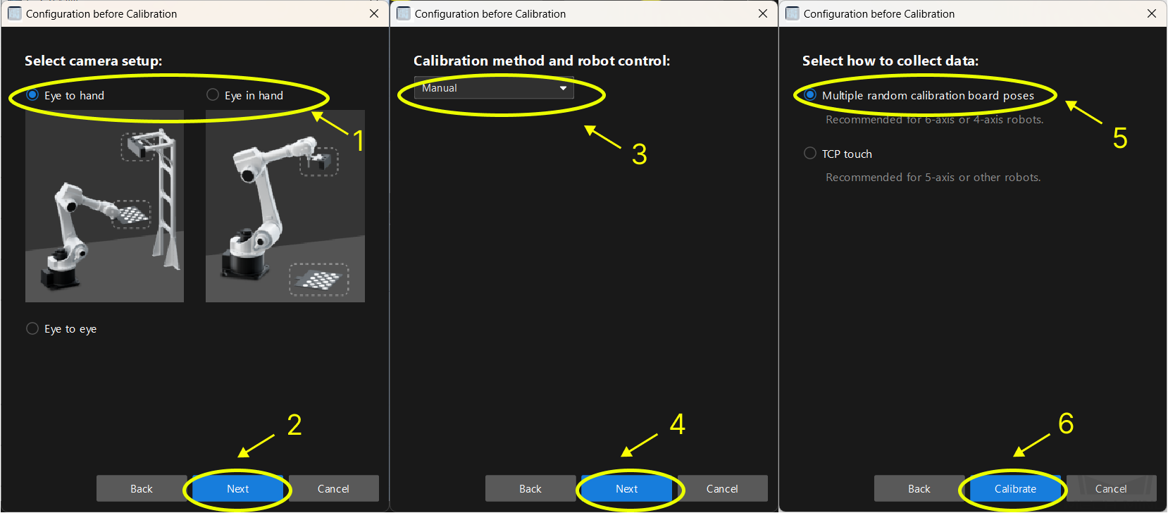
Select the camera’s mounting method (choose Eye to Hand if the camera is mounted on a fixed bracket, or Eye in Hand if it is mounted on the robot), and then click the corresponding button.
-
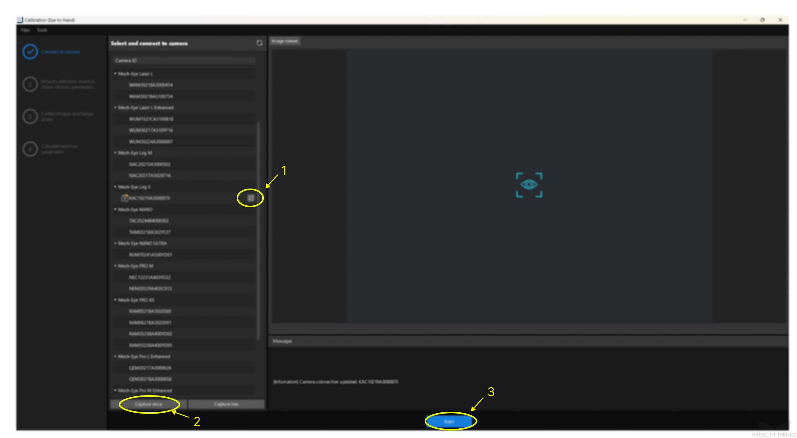
Connect to camera: Select the corresponding camera→Click the “connect” button→Capture once. Then click the Next button after confirming that the 2D image and depth map of the camera are normal.
-
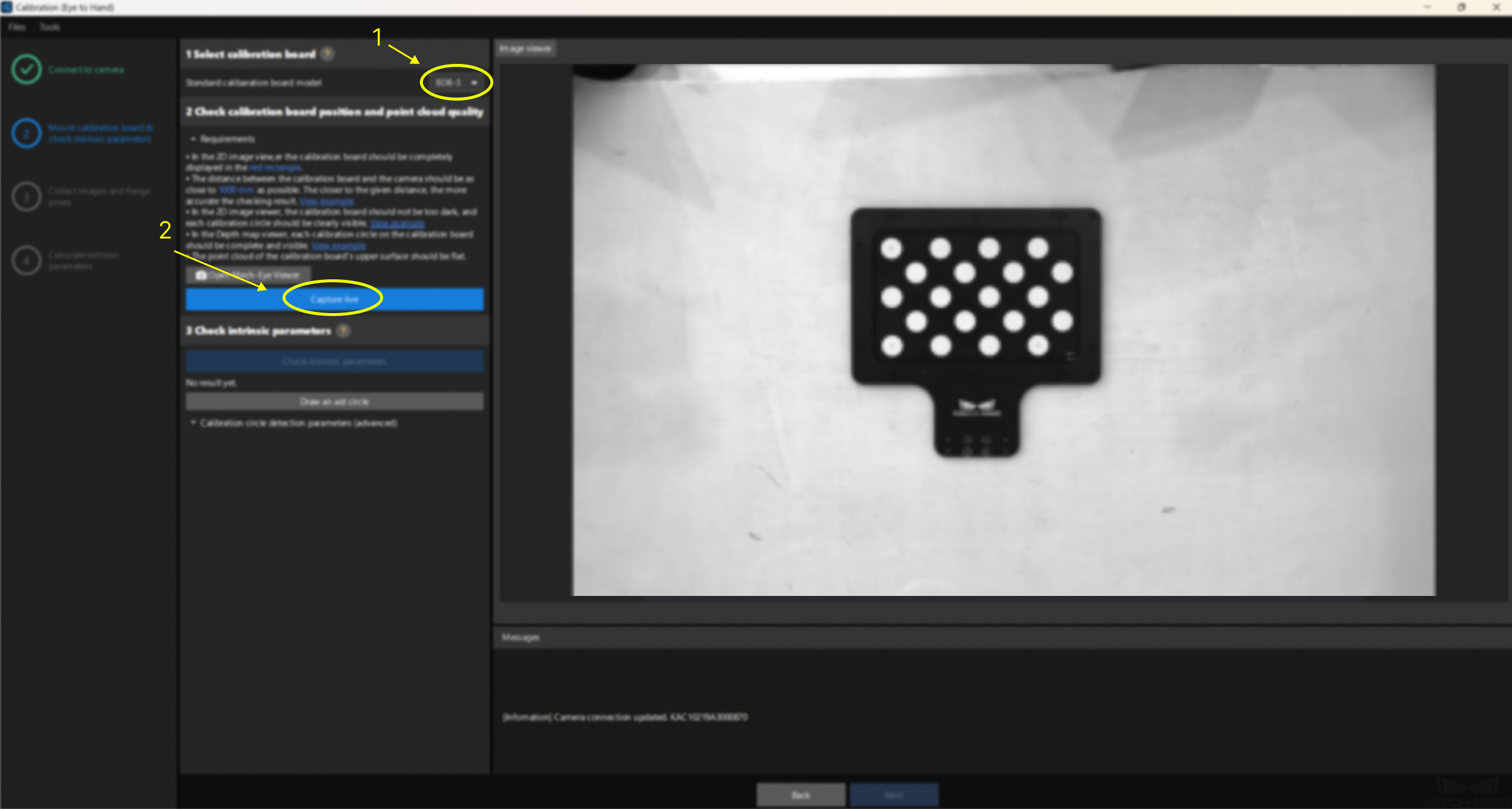
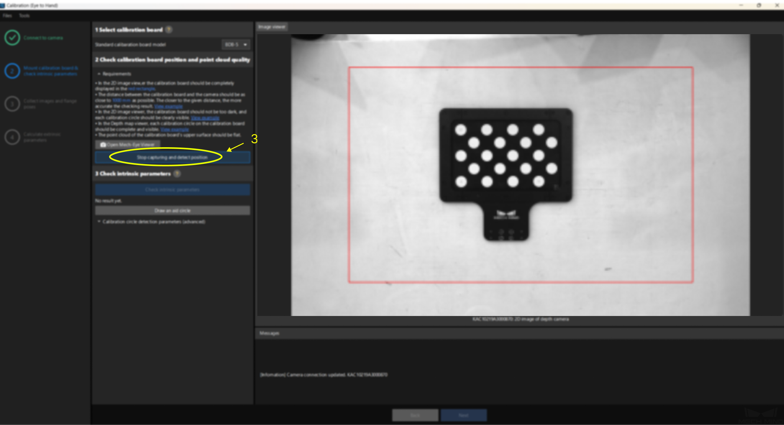
Select the corresponding calibration board model (the model is labeled on the board), and click Capture live, ensuring that the calibration board is within the red frame in the right-side view. Then, click the Stop capturing and detect position button.
-
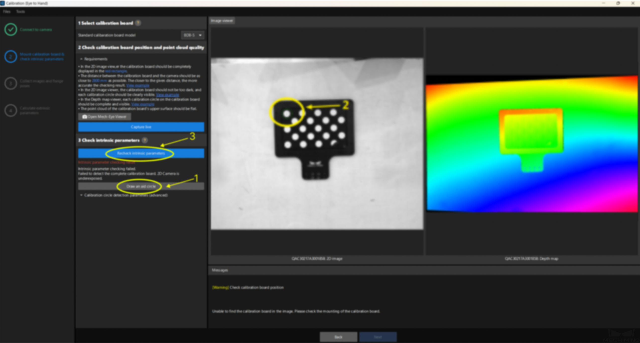
Click Check intrinsic parameters.
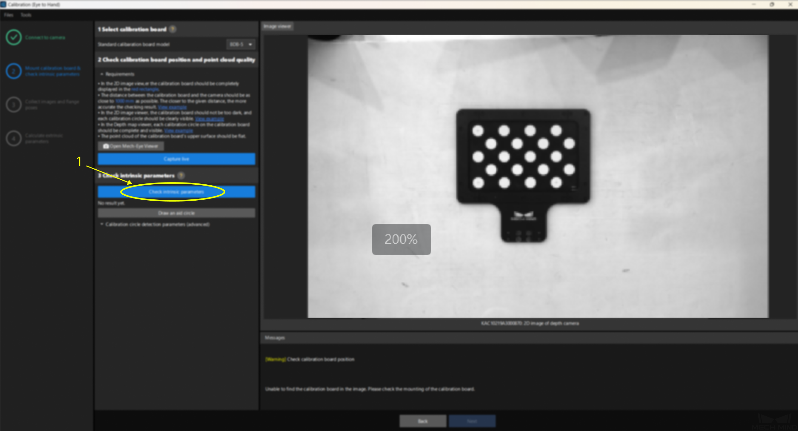
If the detection is successful, it will display as shown below. If the intrinsic parameter error exceeds the normal range, the displayed information will turn red. In this case, you will need to investigate the issue and recalibrate the camera’s intrinsic parameters.
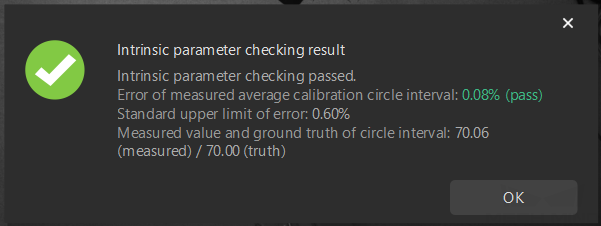
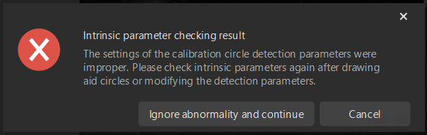
If a detection failure occurs as shown below, click OK, and then proceed with the operation of drawing an aid circle.
-
If the intrinsic parameter check fails, you can draw an aid circle: Click the “Draw an aid circle” button→Use the mouse to draw a circle around a white dot on the right-side calibration board→Click “Check again”.
Extrinsic Parameter Check Method in ETH Setup (Only Applicable When the Robot Has a Model)
-
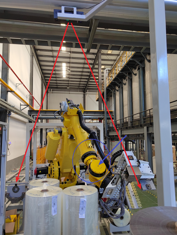
Move the robot body (preferably the five-axis part) into the camera’s field of view, trigger the camera to capture images, and display the robot body’s point cloud in the Mech-Viz software.
-
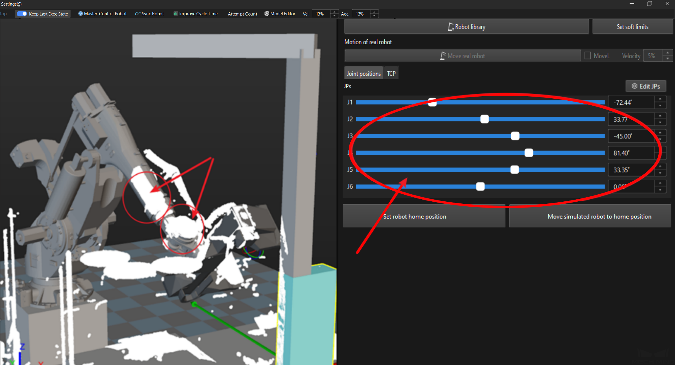
Synchronize the robot within the Mech-Viz software and check the degree of overlap between the point cloud and the robot model. If the degree of overlap is high, then the extrinsic parameters are normal; otherwise, they are abnormal. Note: Due to external factors (such as the robot’s absolute accuracy and the precision of its enclosure), this method should only be used as a rough guideline.
Extrinsic Parameter Check Method in EIH Setup
-
Place the calibration board within the camera’s field of view, capture an image of the board, and display the point cloud in Mech-Viz.
-
Keep the calibration board in the same position and adjust the camera position (translation and rotation) to ensure the board remains within the camera’s field of view. After synchronizing the robot, capture the image and display the point cloud in Mech-Viz.
-
Check if the point clouds of the calibration board before and after are aligned. If so, the extrinsic parameters are normal; otherwise, they are abnormal.