Automatic Hand-Eye Re-Calibration in the Eye-to-Eye Setup
This how-to guide introduces how to complete the automatic hand-eye calibration in the eye-to-eye (ETE) setup.
Preparation before Calibration
Prepare the Materials Required for Calibration
The hand-eye calibration in the ETE setup needs to use the calibration board. Please prepare the calibration board according to the following requirements:
-
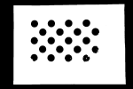
Ensure that the circles of the calibration board are clearly visible and without obvious scratches, and the board does not suffer from deformations.
-
In the ETE setup, mount the robot-specific bracket for calibration board onto the robot flange, and then mount the calibration board onto the bracket. Make sure that the calibration board is attached securely, and that the board is parallel to the XY plane of the robot flange frame.
If an undetachable gripper is connected to the robot flange, you can attach the calibration board directly to the gripper.
In addition, before calibration, move the robot to the starting point for calibration, that is, the bottom middle of the overlapped area of the two cameras’ field of view.
Adjust the Effect of Calibration Board’s Point Cloud
-
Open Mech-Eye Viewer to adjust camera parameters.
-
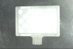
Adjust the 2D parameters to make sure that the 2D image of the calibration board is clear and neither overexposed nor underexposed.
-
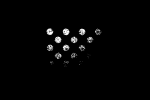
Adjust 3D parameters to make sure that the point clouds of the circles on the calibration board are complete and have clear contours. It is recommended to set Surface Smoothing and Outlier Removal to Normal in the Point Cloud Processing section to reduce the point cloud fluctuation range.
-
Make sure that the images and point cloud of the calibration board are up to standard after completing the preceding steps.
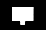
Normal Overexposed Underexposed 2D image
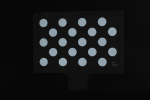

Point cloud
Pre-calibration Configuration
-
Open Mech-Vision, select a project in the project list, and then click the Camera Calibration (Standard) button in the toolbar. The Configuration before Calibration window will be prompted.
-
In the Select how to calibrate window, select the New calibration radio button, and then click the Next button.
-
In the Select calibration task window, select Hand-eye calibration for listed robot from the drop-down list box, click the Select robot model button to select the robot model used by the project, and then click the Next button.
-
In the Select camera setup window, select the Eye to eye radio button, and then click the Next button.
-
In the Calibration method and robot control window, select Automatic and Standard Interface, and then click the Next button.
-
In the Interface Settings window, set parameters Protocol and Host IP address, and then click the `Start interface service` button. The button will turned into Waiting for the robot to connect....
-
On the robot teach pendant, select the automatic calibration program, teach the start point and run the program. For details on the calibration programs of different robots, refer to the section Standard Interface Communication. After the program is started, log message "Entering the calibration process, please start the calibration in Mech-Vision" will be printed in the Console log pane.
-
Return to Mech-Vision, confirm that "Connected" status message is displayed in the Connect the robot area, and click the Calibrate button. The Calibration (Eye to Eye) window will be prompted.
Till now, you have completed the pre-calibration configuration and can start the calibration procedure.
Calibration Procedure
Connect to Camera
-
In the Connect to camera step, select the secondary camera to connect in the Detected cameras list, and then click the
 button or double-click the camera entry to connect to it.
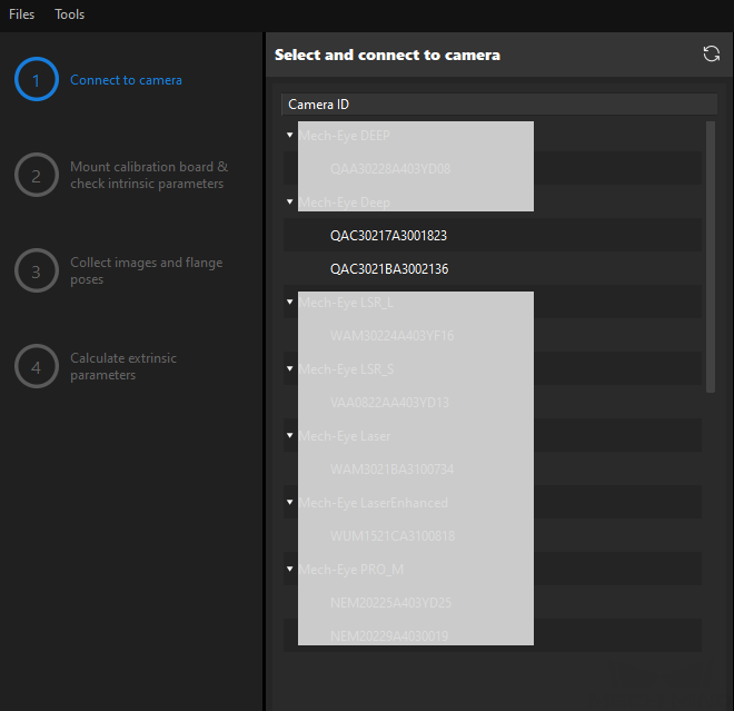
-
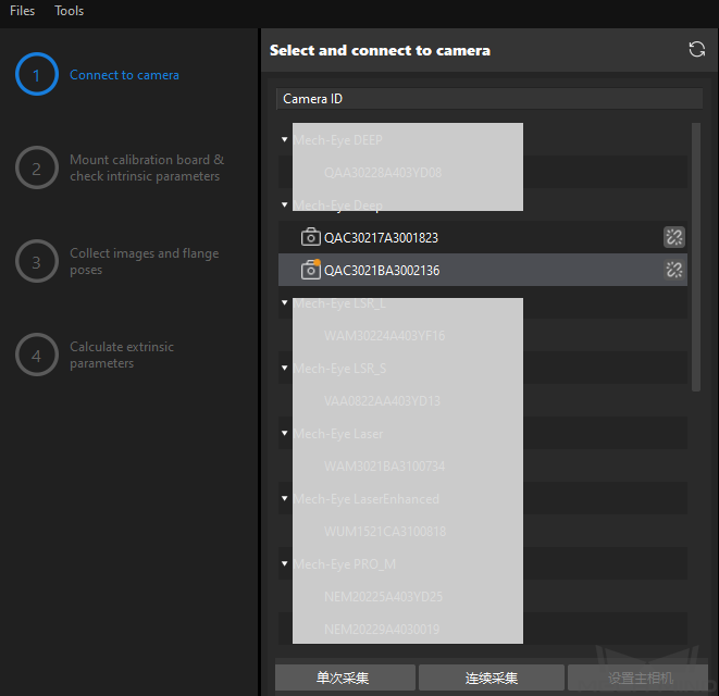
Repeat the preceding step to connect to the primary camera. After the primary camera is connected, the
 icon will be displayed before the camera ID.
To switch the primary camera, select a camera, and then click the Set as main button.
-
After the camera is connected, click the Capture live or Capture once button.
-
In the Image viewer panel, ensure that the camera can capture images normally and click the Next button on the bottom bar.
In this step, the 2D image and depth map are captured only for the primary camera. To confirm the effects of the images captured by the secondary camera, you can switch it to the primary camera, and switch the original primary camera back to the primary camera after confirming.
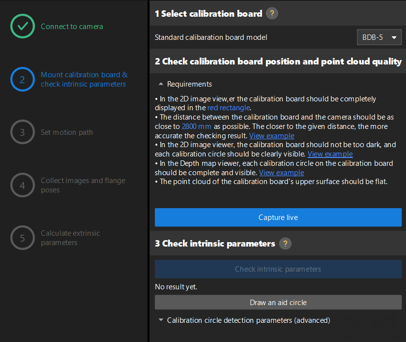
Mount Calibration Board & Check Intrinsic Parameters
-
In the Mount calibration board & check intrinsic parameters step, select the calibration board model for the Standard calibration board model parameter according to its model nameplate in the 1 Select calibration board area.
-
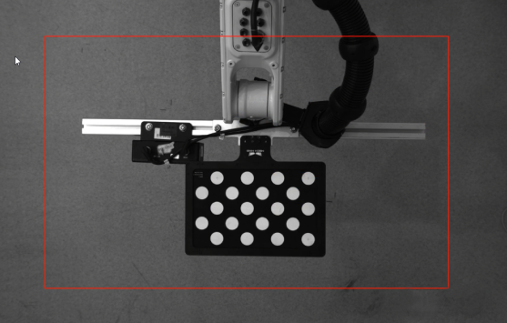
In the 2 Check calibration board position and point cloud quality area, read carefully the requirements on the calibration board position and point cloud quality, and then click the Capture live button. The Capture live button will turn into Stop capturing and detect position.
-
Control the robot to move the calibration board to the proper position (in the red rectangle), and ensure that the 2D image and depth map of the calibration board meet the requirements, and then click the Stop capturing and detect position button.
If the captured images do not meet the requirements, click Open Mech-Eye Viewer button to open the Mech-Eye Viewer software, adjust the 2D and 3D exposure parameters and re-capture images. Please note that you need to change the Parameter group parameter to “calib” first.
-
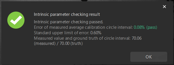
In the 3 Check intrinsic parameters area, click the Check intrinsic parameters button.
-
Confirm the results of the camera intrinsic parameter check.
-
If the camera intrinsic parameter check passes, click the OK button in the prompted window, and then click the Next button on the bottom bar.
-
If the camera intrinsic parameter check fails, adjust detection parameters by drawing aid circles or manually adjusting the calibration circle detection parameters, and then click the Recheck intrinsic parameters button. If the intrinsic parameter check still fails, please contact Technical Support.
-
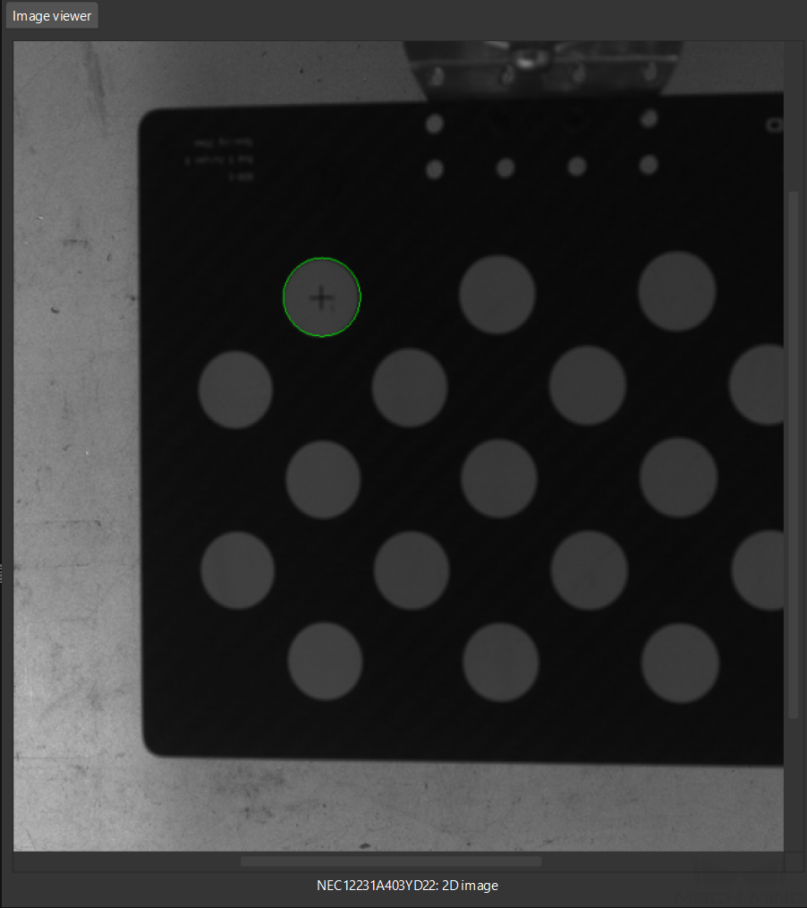
Draw Aid Circle
-
To draw an aid circle, click the Draw an aid circle button.
-
In the right Image viewer panel, right-click the calibration board image, clear the Fit to window checkbox, press the Ctrl key and drag the roller to adjust the image to a suitable size.
-
Move the mouse pointer to the cross center point of the calibration circle, press the left mouse button and make the aid circle completely include the calibration circle and then release it.
-
Click the Recheck intrinsic parameters button, and confirm that the camera intrinsic parameter check passes.
Set Motion Path
-
In the Set motion path step, keep the Height span parameter in the 1 Set height span of calibration poses area unchanged.
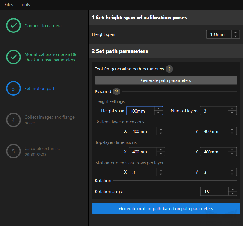
The Height span parameter should be set according to the recommended working distance range of the camera and the size of the robot’s working space.
-
Click the Generate path parameters button, and then click the Generate motion path based on path parameters button.
-
When the Generate motion path based on path parameters turns into Completed, click the Next button on the bottom bar.
Collect Images and Poses
-
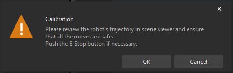
Click the Auto move robot along path and capture images button, read the safety window carefully, and then click the OK button.
-
Wait until the robot finishes moving along the preset path and the camera finishes capturing images on all waypoints. In the right Image viewer panel, all the captured images are displayed.
-
Please stay away from the robot working area to keep safe.
-
Clicking the Stop robot button can exit the calibration process. But the robot will not stop until it finishes the current waypoint. In case of emergency, please tap the emergency stop button on the robot teach pendant to stop the robot immediately (the robot needs to be reconnected after tapping the emergency stop button).
-
-
After all images are captured, click the OK button in the prompted window.
-
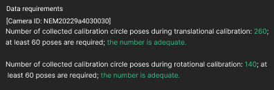
Confirm that the collected calibration data meets the data requirements, and then click the Next button on the bottom bar.
Calculate Extrinsic Parameters
-
In the Calculate extrinsic parameters step, click the Calculate extrinsic parameters button.
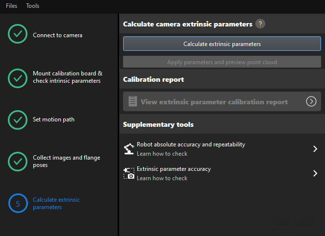
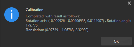
-
In the prompted window indicating calibration success, click the OK button.
-
Click the Save button on the bottom bar. In the prompted Save Calibration Files dialog box, click the OK button. The camera calibration result will be automatically saved in the “calibration” directory of the project.
|
Till now, the calibration process is completed.
Calculate Pose Relationship between Cameras from the Calibrated Extrinsic Parameters Directly
After calibrating the extrinsic parameters of the two cameras separately, you can use the ETE calibration procedure to directly calculate the pose relationship between the two cameras.
To do so, follow these steps:
-
Open Mech-Vision, and click the Camera Calibration (Standard) button in the toolbar. The Configuration before Calibration window will be prompted.
-
In the Select how to calibrate window, select the New calibration radio button, and then click the Next button.
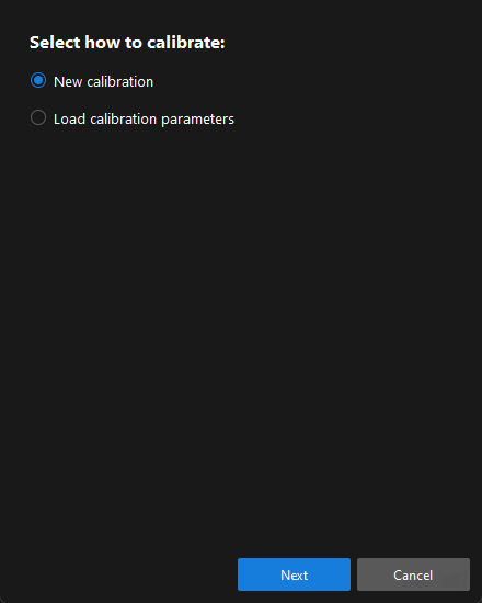
-
In the Select calibration task window, select Hand-eye calibration for custom robot from the drop-down list box, specify the Robot Euler angle convention parameter, select the robot coordinate system type, and then click the Next button.
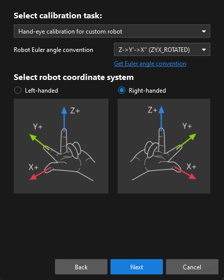
-
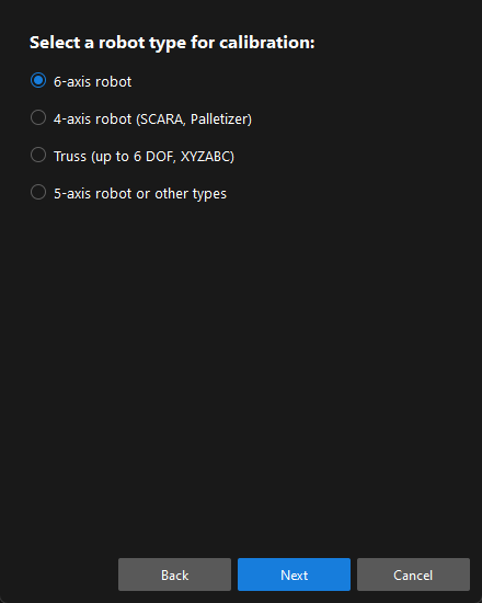
In Select a robot type for calibration window, select a robot type among 6-axis robot, 4-axis robot (SCARA, Palletizer) or 5-axis robot or other types radio button, and then click the Next button.
-
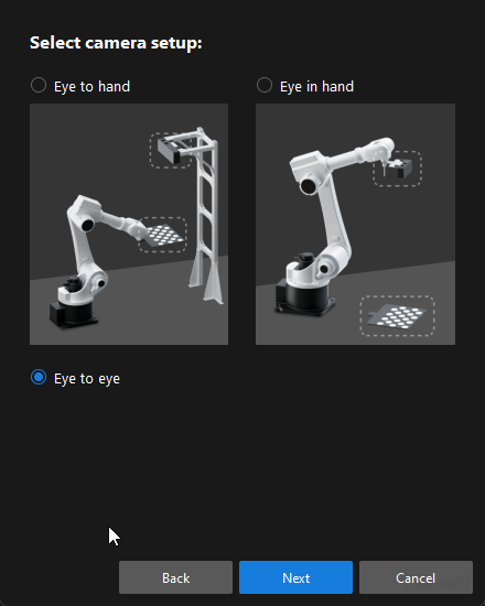
In the Select camera setup window, select the Eye to eye radio button, and then click the Next button.
-
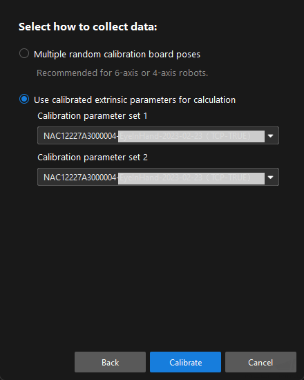
In the Select how to collect data window, select the Use calibrated extrinsic parameters for calculation, choose two camera’s extrinsic parameter files, and then click the Calibrate button. The Calibration (Eye to Eye) window will be prompted.
-
In the Connect to camera step, select the camera to connect in the Camera ID list, and then click the
button to connect to it. -
Repeat the preceding step to connect to the second camera, and then click the Next button on the bottom bar.
-
In the Calculate extrinsic parameters step, click the Calculate extrinsic parameters button.
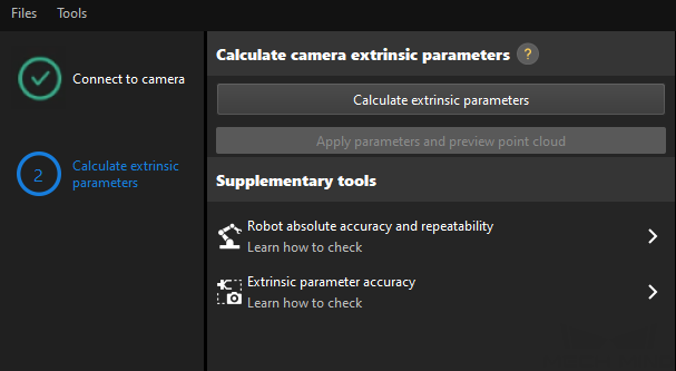
After the camera extrinsic parameters have been calculated, you can view the fused point cloud in the Point cloud viewer panel.
Change the Extrinsic Parameter File
After hand-eye calibration, it is necessary to change the extrinsic parameter file used in the current Mech-Vision project to a new one.
-
Select the Capture Images from Camera Step.
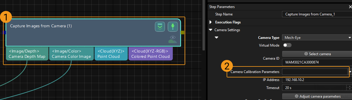
-
In the Step Parameters panel, click
 of the Camera Calibration Parameters parameter, and select the newly calibrated extrinsic parameter file.
Calibration-Related Status Codes
If the robot uses the Standard Interface to communicate with the Vision System during hand-eye calibration, the Vision System will return status codes in response data to indicate the execution status of the commands. The status codes indicate both the normal execution results and execution failures. You can perform further troubleshooting according to the status codes.
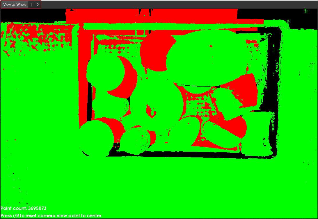
Check the Fusion Effect of the Calibration in the ETE Setup Using a Mech-Vision Project
You can build a project as shown in the following figure. Note that the "Trigger Control Flow Given No Output" and "Trigger Control Flow Given Output" options in Execution Flags area should be selected.
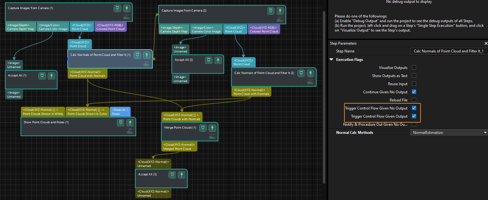
Execute the single Step “Merge Point Clouds” to display the fused point cloud. The point cloud output after merging is the fused whole point cloud, as shown in the figure below. You can click the upper left corner View as Whole| 1 | 2 to switch point clouds.