Add Pick Point by Teaching under EIH Mode + Generate Point Cloud Model from Images Captured by the Camera
Add Pick Point by Teaching under EIH
Preparation
-
Start the robot, acquire the TCP data from the teach pendant, and record it. If you are using Mech-Viz, you can check the TCP by going into Mech-Viz Project resource tree > Tools and double-clicking the corresponding tool model.
-
Open Matching Model and Pick Point Editor.
-
Start Mech-Vision.
-
Open an existing project or create a new blank project, ensuring it includes the “Capture Images from Camera” Step. If this step is not present, please add it.
-
Click Matching Model and Pick Point Editor on the toolbar.
-
-
Place the target object within the camera’s field of view.
Workflow
-
In the initial interface of the Matching Model and Pick Point Editor, click “Capture point cloud”;
-
In the pop-up window, click Teach the Pick Point and capture point cloud;
-
Click Teach the Pick Point;
-
Enter the corresponding data in the TCP field;
-
Set picking pose
-
Move the robot close to the target object using the teach pendant. Operate the end effector to perform a picking test, ensuring that it can securely pick the object at the pick point.
-
In the Picking pose section, click Fetch current pose, or input the pose displayed on the teach pendant manually.
-
-
Set image capturing pose
-
Use the teach pendant to move the robot to a position where it can take a picture with the camera. Be careful not to touch the target object in this process to avoid altering its pose.
-
In the Image capturing pose section, click Fetch current pose, or input the pose displayed on the teach pendant manually.
-
-
Click Confirm to generate a pick point.
Generate Point Cloud Model from Images Captured by the Camera
Adjust Camera Parameters
Preparation
-
Lighting conditions: Ensure that the lighting around the target object is even and not too dark or too bright.
-
Target object placement: Place the target object within the camera’s field of view and ensure that its positioning highlights the key features of the target object.
-
Background selection: Ensure that the target object is easily distinguishable from the background.
Adjust Camera Parameters
-
Open Mech-Eye Viewer and connect the camera;
-
 : Acquire data once;
 -
Click point cloud to check the effect.
√
×
The target object is outside the camera’s field of view. At this time, it is necessary to place the target object within the camera’s field of view.
×

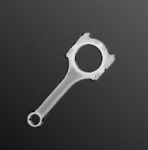
The exposure time parameter is set too low. At this point, you need to increase the exposure time in the 3D parameters.
×
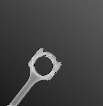
The exposure time parameter is set too high. At this point, you need to decrease the exposure time in the 3D parameters.
×
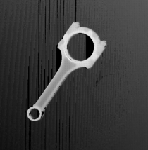
The point cloud information of the target object is incomplete. Try to slightly adjust the exposure time in the 3D parameters.
-
Keep capturing until you acquire point clouds with relatively high quality.
Acquire Point Cloud
Preparation
-
Start Mech-Vision.
-
Open an existing project or create a new blank project, ensuring it includes the “Capture Images from Camera” Step. If this step is not present, please add it.
-
Click Matching Model and Pick Point Editor on the toolbar.
Acquire Point Cloud
-
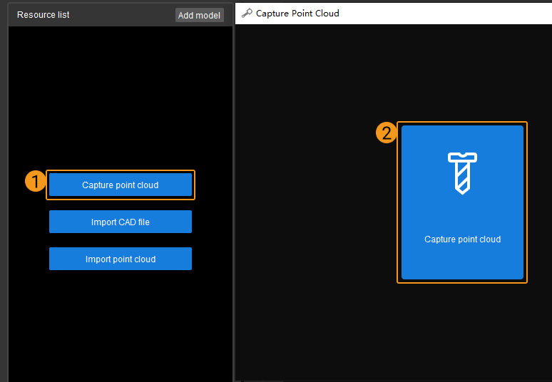
Click the Capture point cloud button in the start screen, and select Capture point cloud in the pop-up window.
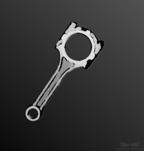
When the target object is flat but shows clear and fixed edge characteristics in the images (such as panels, track shoes, connecting rods, brake discs, etc.), it is recommended to use an edge model, namely selecting “Use edge point cloud”. When the surface of the target object has many undulations (such as crankshafts, rotors, steel rods, etc.), it is recommended to use a surface model.
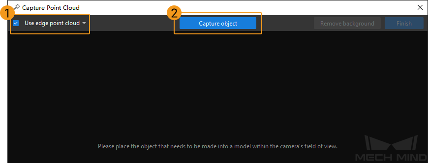
Due to the complex surface features of the track link used in the example, it is recommended to create a surface point cloud model for this target object. Therefore, clear the ]Use edge point cloudbtn:[ checkbox. Then click the Capture object button to capture the depth map of the target object.
-
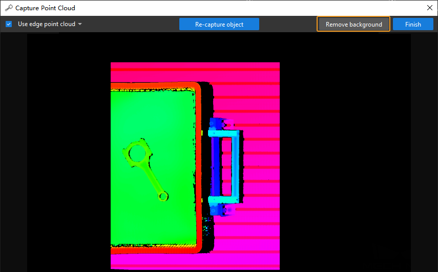
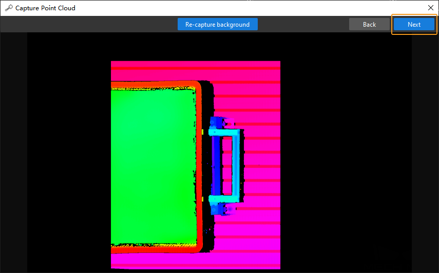
The captured depth map of the target object and background is shown as below.
-
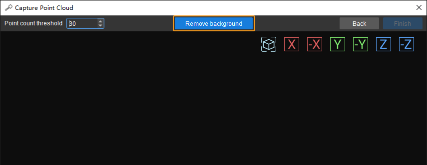
In the upper-right corner, click the Remove background button.

-
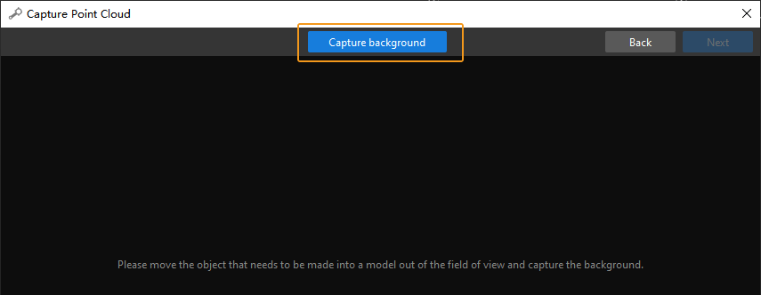
Remove the target object in the camera’s field of view first, and click Capture background again to capture a depth map of the background.
-
The depth map of the background is shown as below. Then, click the Next button in the upper-right corner.
-
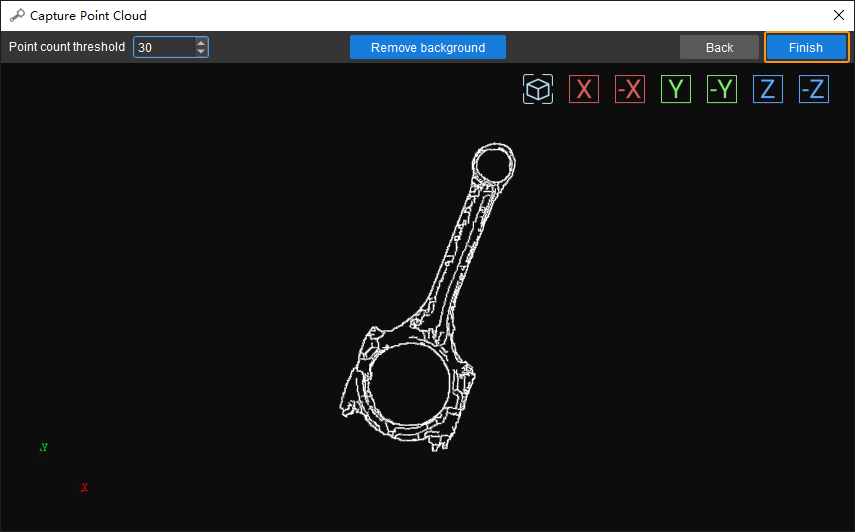
Click Remove background to generate a point cloud model of the target object, as shown below.
-
Click Finish to import the point cloud model of the target object to Matching Model and Pick Point Editor.
Edit Point Cloud
The model point cloud captured in the last Step may not meet the actual requirement. In such case, you need to edit the model, including removing outliers and downsampling the point cloud.
-
Remove outliers
Click the
 button, select outliers to remove, and then click the
  button to remove selected points.
As shown in the figure below, selected points are outliers and can be removed by following this step.
button to remove selected points.
As shown in the figure below, selected points are outliers and can be removed by following this step.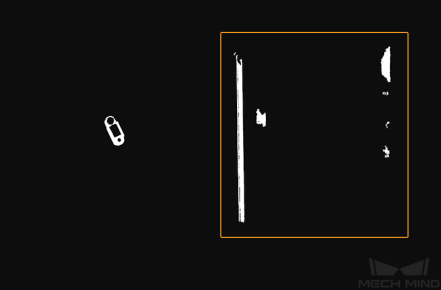
-
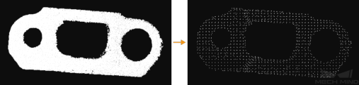
Point cloud downsampling
Point cloud downsampling aims to reduce the number of points in the point cloud model, thus improving model matching efficiency. Click the
 button and set the sampling interval in the pop-up window.
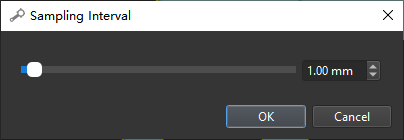
In the figure below, the left image is a point cloud model before downsampling, and the right one is after downsampling with a sampling interval of 3 mm.