UR CB-Series (PolyScope 3.9 or Above)
Plugin Installation and Setup
This section introduces the installation and setup of Mech-Mind 3D Vision Interface (URCap plugin) for UR CB-series.
Prerequisites
Verify that you meet the minimum required versions for Mech-Mind vision-series software and Polyscope.
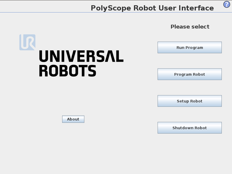
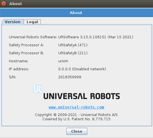
To view the version of Polyscope, press About on the Polyscope home screen of the UR teach pendant.
Install the URCap Plugin
To install the URCap plugin, follow these steps:
-
Find the URCap plugin file with the extension “.urcap” in
Communication Component\Robot_Interface\Robot_Plugin\UR_URCAP\Polyscopein the installation directory of Mech-Vision & Mech-Viz, and copy the file to the USB flash drive. -
Insert the USB drive into the UR teach pendant.
-
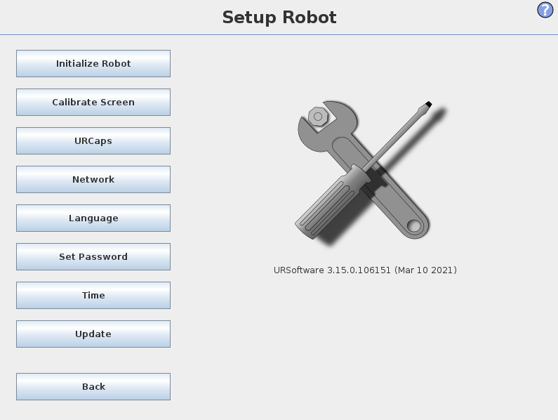
On the Polyscope home screen, press Setup Robot.
-
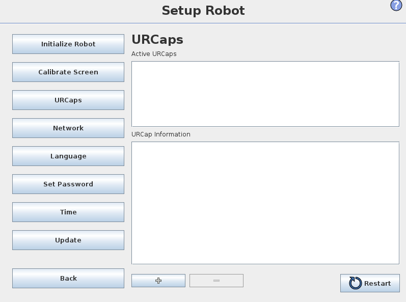
In the Setup Robot window, select URCaps on the left panel.
-
In the URCaps window, press + to navigate to the USB drive to locate the URCap plugin (.urcap file).
-
In the Select URCap to install window, select the URCap plugin and press Open. The URCap plugin will be automatically installed.
-
Press Restart for the change to take effect.
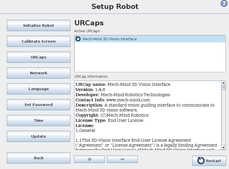
Till now, the URCap plugin is successfully installed on the UR teach pendant.
| After installing the URCap plugin, you also need to set the IP address of the robot (select Set Robot > Network). Note that the robot’s IP address and the IPC’s IP address must be on the same subnet. |
Use Mech-Mind 3D Vision Interface
|
Before use, make sure that your Mech-Vision and Mech-Viz (if used) projects are ready to run, and the Mech-Mind IPC is connected to the robot’s network. |
To use Mech-Mind 3D Vision Interface, you need to complete the following setup.
-
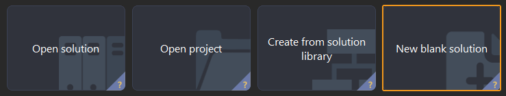
Open Mech-Vision, and you may enter different interfaces. Create a new solution according to the instructions below.
-
If you have entered the Welcome interface, click New blank solution.
-
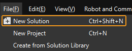
If you have entered the main interface, click on the menu bar.
-
-
Click Robot Communication Configuration on the toolbar of Mech-Vision.
-
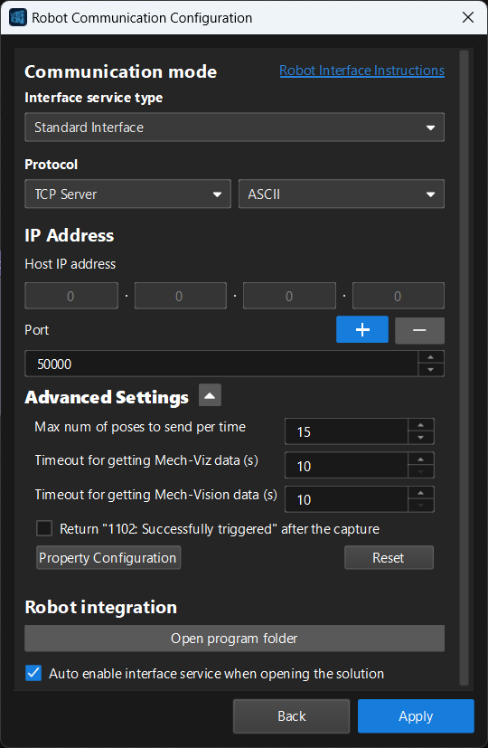
In the Robot Communication Configuration window, complete the following configurations.
-
Click the Select robot drop-down menu, and select Listed robot. Click Select robot model, and select the robot model that you use. Then, click Next.
-
In the Communication mode section, select Standard Interface for Interface service type, TCP Server for Protocol, and ASCII for the protocol format.
-
In the Advanced Settings section, set Max num of poses to send per time to 15.
-
Set the port number to 50000 (fix valued). Ensure that the port number is not occupied by another program.
-
(Optional) Select Auto enable interface service when opening the solution.
-
Click Apply.
-
-
On the main interface of Mech-Vision, make sure that the Robot Communication Configuration switch on the toolbar is flipped and has turned blue.
After the TCP server interface has been started in Mech-Vision, you can connect to it on the UR teach pendant.
-
On the Polyscope home screen, press Program Robot.
-
Select the Installation tab, and select Network Settings on the left panel. The Network Settings window of the URCap plugin is displayed.
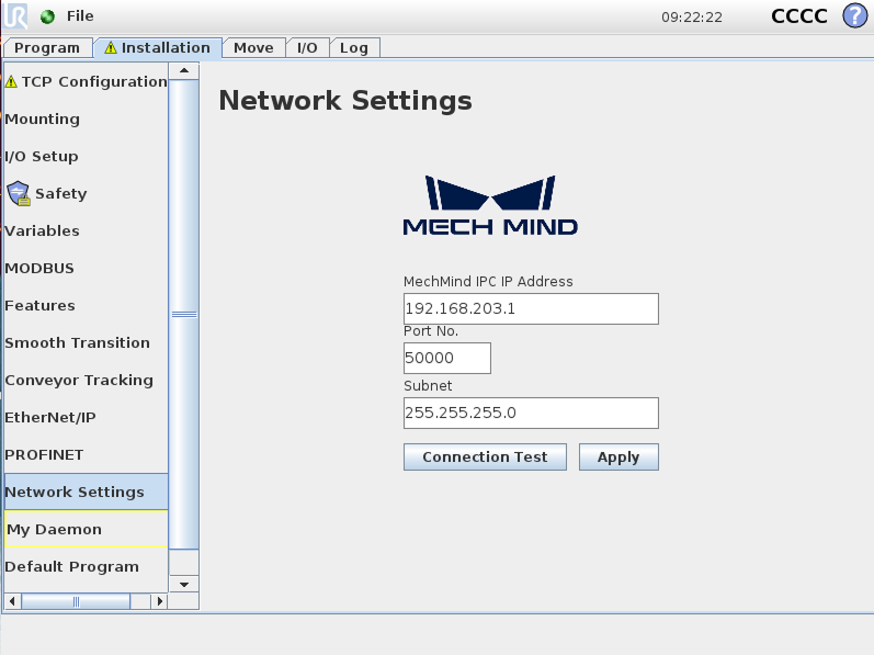
-
Set MechMind IPC IP Address and Port No. to the IP address and port number of the Mech-Mind IPC respectively, and press Apply. The port number here and set in Mech-Vision must be the same. Then, press Apply.
-
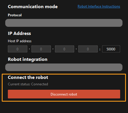
Press Connection Test.
-
When the connection to the TCP server interface is established successfully, the return status should look like this:

-
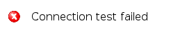
When the connection to the TCP server interface fails to be established, the return status should be like this:
The connection test is just for testing. Once connected, it will disconnect automatically. Therefore, you will see client online and offline logs on the Console tab of Mech-Vision Log panel.
-
Hand-Eye Calibration Using the Plugin
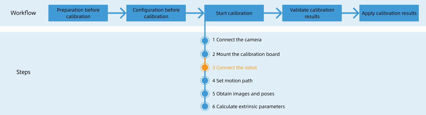
After you set up Standard Interface communication, you can connect the robot to perform automatic calibration. The overall workflow of automatic calibration is shown in the figure below.
Special note
During the calibration procedure, when you reach the Connect the robot step and the Waiting for robot to connect... button appears in Mech-Vision, perform the steps below on the robot side. After you perform the steps, proceed with the remaining steps in Mech-Vision.
|
Create a Calibration Program
-
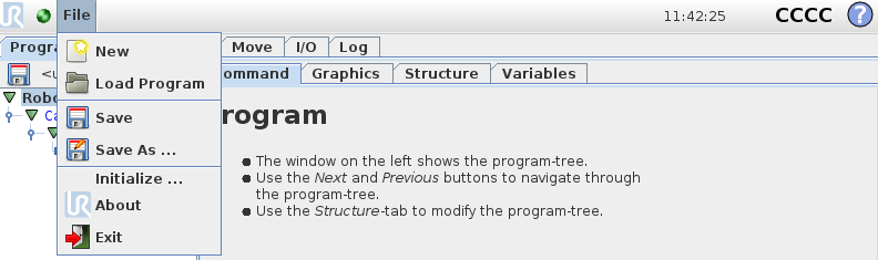
On the UR teach pendant, select , and press Empty Program.
-
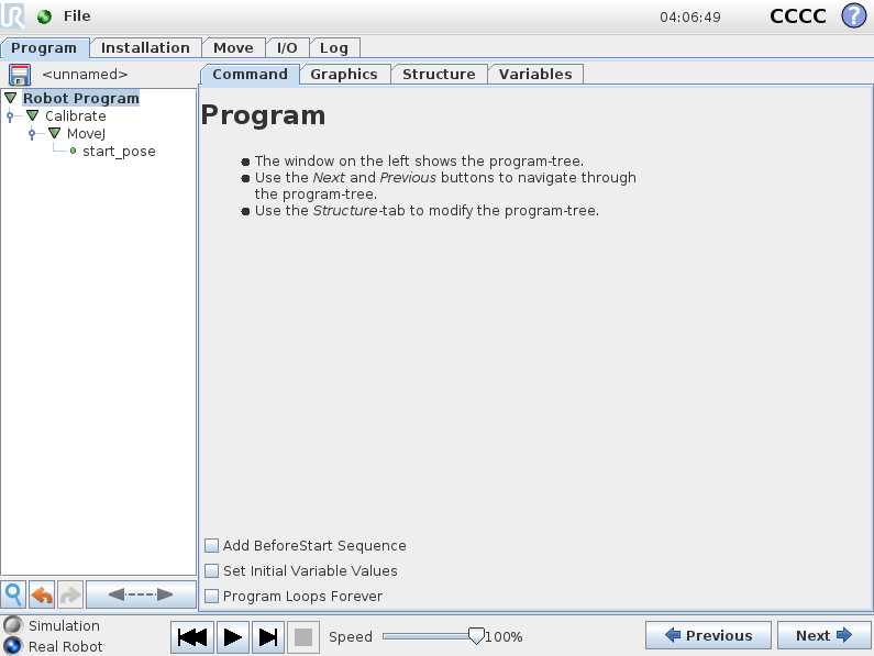
Select and select Mech-Mind Calibrate under the URCaps tab. An example program node Calibrate is automatically created in the Robot Program section on the left panel.
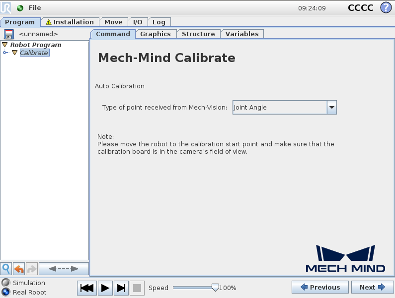
The created example program node is just a template. You need to further configure the calibration program and teach the calibration start point.
Teach Calibration Start Point
-
Double-click the Calibrate node. In the right-side panel, select the Command tab. Set Type of point received from Mech-Vision based on actual needs.
-
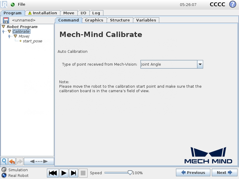
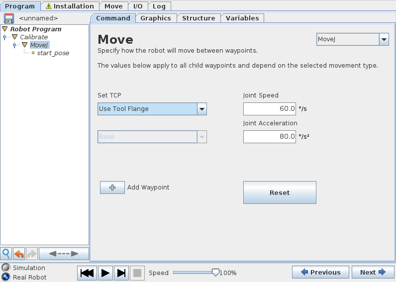
Press Next on the bottom bar to proceed to the MoveJ node. Set the move type (MoveJ, MoveL, or MoveP), and configure Set TCP to Use Tool Flange on the right Move panel to ensure that the waypoint will be recorded as a flange pose.
-
Manually control the robot to move to the start point for the calibration.
You can use the position of the robot in the Check the Point Cloud Quality of the Calibration Board step as the calibration start point.
-
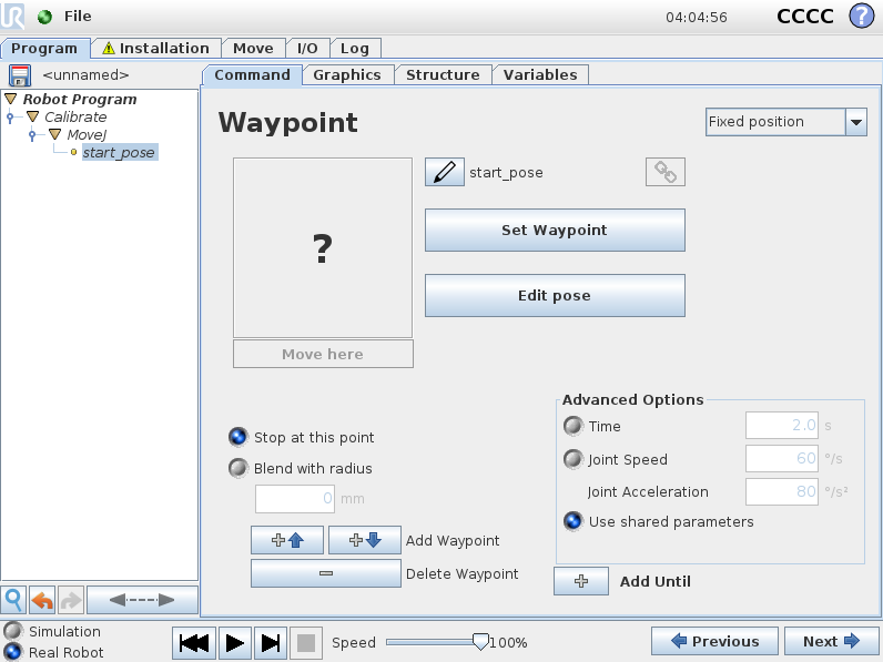
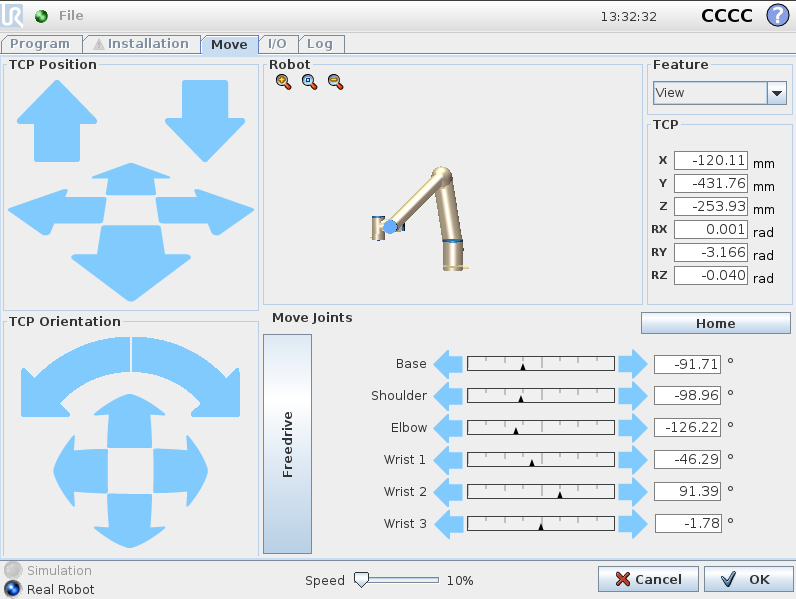
Go back to the UR teach pendant, select the start_pose node on the left panel, and then press Set Waypoint on the right Waypoint panel. You will be switched to the Move tab.
-
On the Move tab, confirm that the robot’s current flange pose is proper and press OK.
Run Calibration Program
-
Select the Robot Program program tree on the left panel, and clear the Program Loops Forever checkbox on the right Program panel to ensure that the program is run just once.
-
On the bottom bar, lower the robot speed to a proper value, such as 10%, for safety concerns.
-
Press
 on the bottom bar to run the program.
 -
When, in the Calibration window in Mech-Vision, the current status changes to connected and the button Waiting for the robot to connect... changes to Disconnect robot, click Next at the bottom.
-
Perform Step 4 of Start calibration (which is Set motion path) and the subsequent operations based the following links.
-
If the camera mounting mode is eye to hand, see this document and proceed with the relevant operations.
-
If the camera mounting mode is eye in hand, see this document and proceed with the relevant operations.
-
To save the calibration program for future use, select to save it.
After you complete the hand-eye calibration, you can create pick and place programs to instruct UR robots to execute vision-guided pick and place tasks.
Create Pick and Place programs
The URCap plugin provides an example Pick and Place program node for you to create pick and place programs with minimal programming efforts.
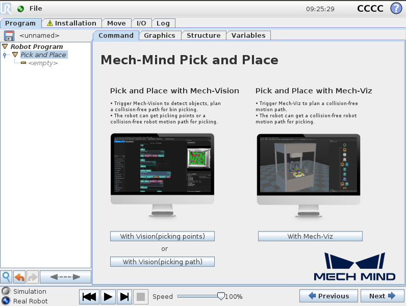
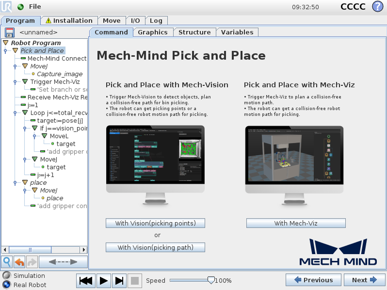
This Pick and Place program node provides three options:
-
Pick and Place with Mech-Vision (picking points): it suits scenarios where only a Mech-Vision project is used (“Path Planning” Step is not included) and the robot does not need Mech-Viz to plan path.
-
Pick and Place with Mech-Vision (picking path): it suits scenarios where only a Mech-Vision project is used (“Path Planning” Step is included) and the robot does not need Mech-Viz to plan path.
-
Pick and Place with Mech-Viz: It suits scenarios where a Mech-Viz project is used together with a Mech-Vision project to provide the collision-free motion path for the robot.
|
Create a Pick and Place with Mech-Vision (picking points) Program
To create a Pick and Place with Mech-Vision (picking points) program, follow these steps:
-
Enable the With Vision (picking points) option.
-
On the UR teach pendant, select .
-
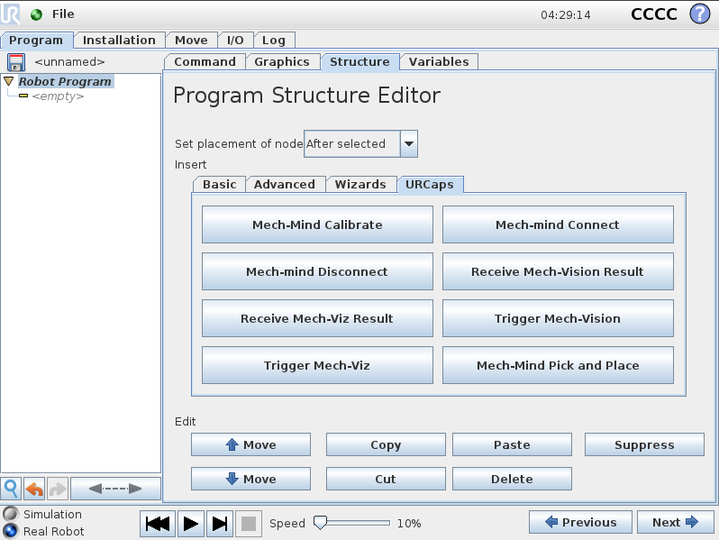
Select , and press Mech-Mind Pick and Place under the URCaps tab. A Pick and Place program node is then added to the Robot Program on the left panel.
-
Select the Command tab, and press the With Vision (picking points) button on the right panel.
-
When you see that a program template is automatically created under the Pick and Place node in the program tree, press Next on the bottom bar.

-
-
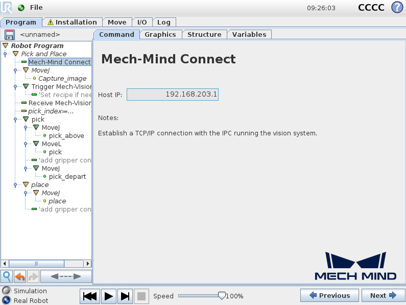
At the Mech-Mind Connect node, verify that the Host IP setting is the IP address of the IPC on the right Mech-Mind Connect panel.
-
Set the image-capturing pose.
-
Manually move the robot to a proper location where Mech-Vision triggers the camera to capture an image.
-
For Eye-In-Hand scenario, the robot should be placed above the workpiece.
-
For Eye-To-Hand scenario, the robot should not block the camera view.
-
-
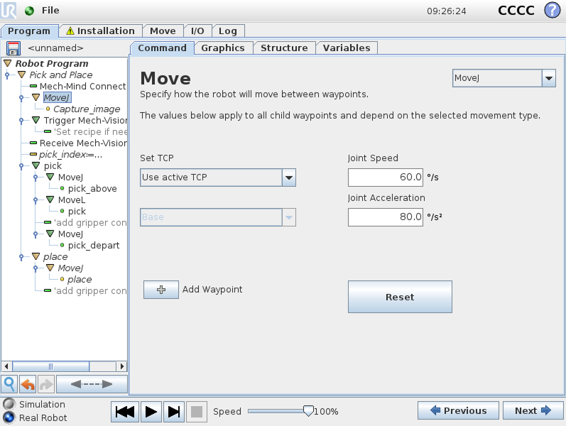
Return to the UR teach pendant, and press Next to proceed to the MoveJ node. On the right Move panel, set the move type (MoveJ, MoveL, or MoveP), and configure Set TCP to Use active TCP, and then press Next.
-
Press Set Waypoint on the right Waypoint panel. You will be switched to the Move tab.
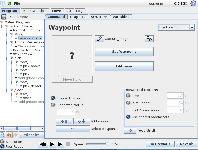
-
On the Move tab, confirm that the robot’s current TCP is proper and press OK.
-
Once the image capturing pose is set, press Next.
-
-
Trigger the Mech-Vision project to run.
-
Set the Type of robot pose to send, Mech-Vision Project ID, and Num of expected poses parameters on the right Trigger Mech-Vision panel. The following table describes the parameters.
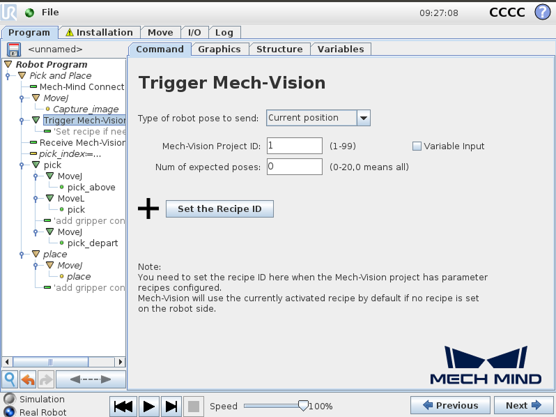
Parameter Description Type of robot pose to send
Specify the type of robot pose to be sent to the Mech-Vision project. In this example, select Current position.
-
Current position: Send the robot’s current joint positions and flange pose to the Mech-Vision project. This setting should be used when the camera is mounted in eye in hand mode.
-
Predefined JPs: Send the custom joint positions to the Mech-Vision project. These joint positions will be sent to the Path Planning Step in the Mech-Vision project as the start point, where the robot will move from this start point to the first waypoint of the planned path. This setting should be used when the camera is mounted in eye to hand mode, the project includes a "Path Planning" Step, and pre-capture is required.
Mech-Vision project ID
The index of the Mech-Vision project to trigger. You can find the project ID in the Project List panel of Mech-Vision.
Num of expected poses
The number of poses expected to be output by Mech-Vision.
-
If set to 0, Mech-Vision will return all recognized poses.
-
If set to an integer between 1 and 20, Mech-Vision will return the specified number of poses when the total number of recognized poses exceeds the expected value. If the total number of recognized poses is less than the expected value, Mech-Vision will return all recognized poses.
-
-
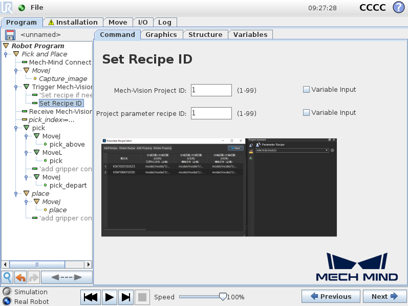
(Optional) Press Set the Recipe ID and a Set Recipe ID node are added under the Trigger Mech-Vision node in the program tree.
Double-click the Set Recipe ID node, and set the values for the Project Parameter Recipe ID on the right Set Recipe ID panel. The value of the Mech-Vision Project ID parameter must be consistent with the value set in the previous node, Then, press Next.
-
-
Set how to receive Mech-Vision result.
Double-click the Receive Mech-Vision Result node, set the Result type and Return pose type, then set the name of the variables for saving returned data. Finally, press Next.
Since the function of this example is to obtain picking points from Mech-Vision, the Result type can only be set to Basic or Custom, and cannot be set to Planned path. 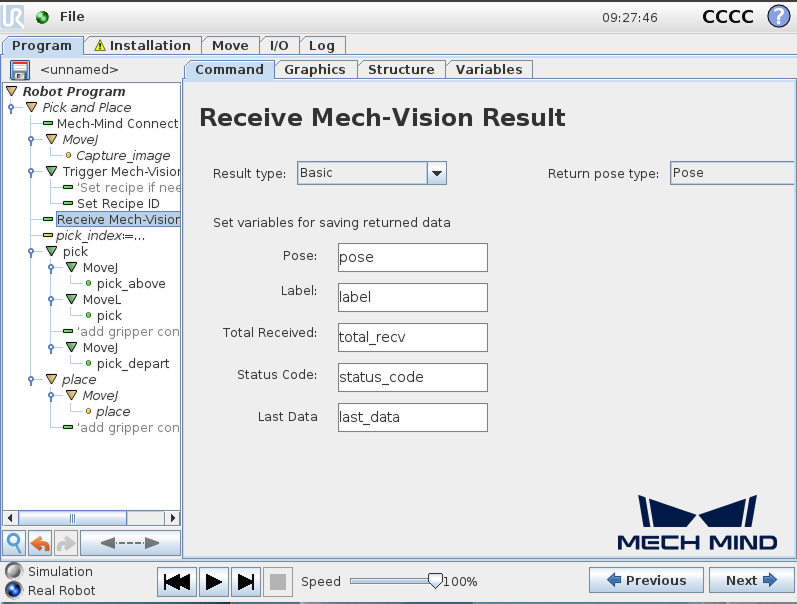
-
When the Result type is set to Basic, the Return pose type can only be set to Pose, it indicates that the received pose type is the TCP. Explanations for other parameters are shown in the table below.
Parameter Description Pose
The pose here refers to the robot’s TCP. The poses output by Mech-Vision (i.e., the data from the poses port of the “Output” Step) will be automatically converted by the vision system into the corresponding robot’s TCP. The robot with the active TCP can move directly to the pose obtained here. By default, the poses are saved in the array variable pose[], with the array starting index as 1.
Label
The label corresponds to each pose. Its value is an integer. By default, labels are saved in the array variable label[], with the array starting index as 1.
Total Received
The number of poses received from Mech-Vision. By default, saved in the variable total_recv.
Status Code
The status code returned by Mech-Vision. Codes starting with 11xx indicate normal status, while codes starting with 10xx indicate errors. For detailed information, refer to the Status Codes and Troubleshooting. By default, the status code is saved in the variable status_code.
Last Data
Indicates whether all recognized poses have been received from Mech-Vision. The value is either 0 or 1, where 0 means not all poses are received, and 1 means all poses are received. By default, this information is saved in the variable last_data.
-
When the Result type is set to Custom, the Return pose type can only be set to Pose, it indicates that the received pose type is the TCP. Explanations for other parameters are shown in the table below. Additionally, you must set Port Type of the Output Step to Custom and select the poses port in the Predefined Keys section in Mech-Vision.
Parameter Description Pose
The pose here refers to the robot’s TCP. The poses output by Mech-Vision (i.e., the data from the poses port of the “Output” Step) will be automatically converted by the vision system into the corresponding robot’s TCP. The robot with the active TCP can move directly to the pose obtained here. By default, the poses are saved in the array variable pose[], with the array starting index as 1.
Label
The label corresponds to each pose. Its value is an integer. By default, labels are saved in the array variable label[], with the array starting index as 1.
Custom Data
The custom data associated with the pose. By default, custom data is saved in the array variable custom_data[], with the array starting index as 1.
Total Received
The number of poses received from Mech-Vision. By default, saved in the variable total_recv.
Status Code
The status code returned by Mech-Vision. Codes starting with 11xx indicate normal status, while codes starting with 10xx indicate errors. For detailed information, refer to the Status Codes and Troubleshooting. By default, the status code is saved in the variable status_code.
Last Data
Indicates whether all recognized poses have been received from Mech-Vision. The value is either 0 or 1, where 0 means not all poses are received, and 1 means all poses are received. By default, this information is saved in the variable last_data.
-
-
Set the first picking point.
Double-click the pick_index:=…*node, and set the *Expression value to 1 on the right panel, then press Next.
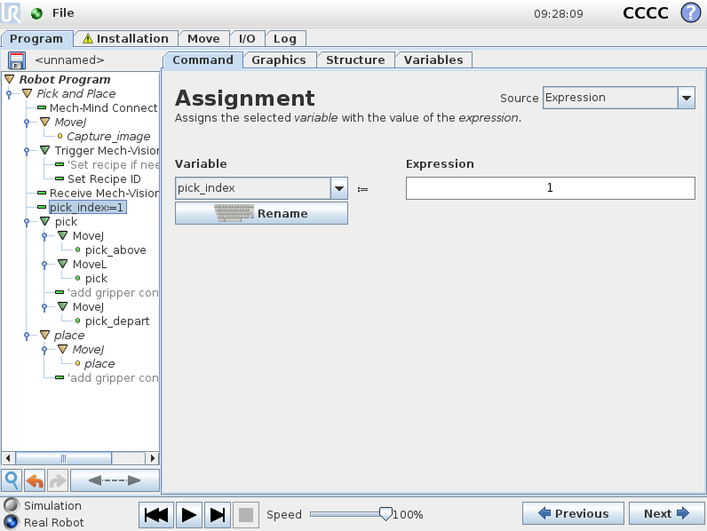
The pick_index is used to assign a value to the pick variable. A value of 1 means the pose of the first received picking point will be assigned to the pick variable, a value of 2 means the pose of the second received picking point will be assigned to the pick variable, and so on. This setting is used to extend the example program with a loop to enable multiple picks from a single image. -
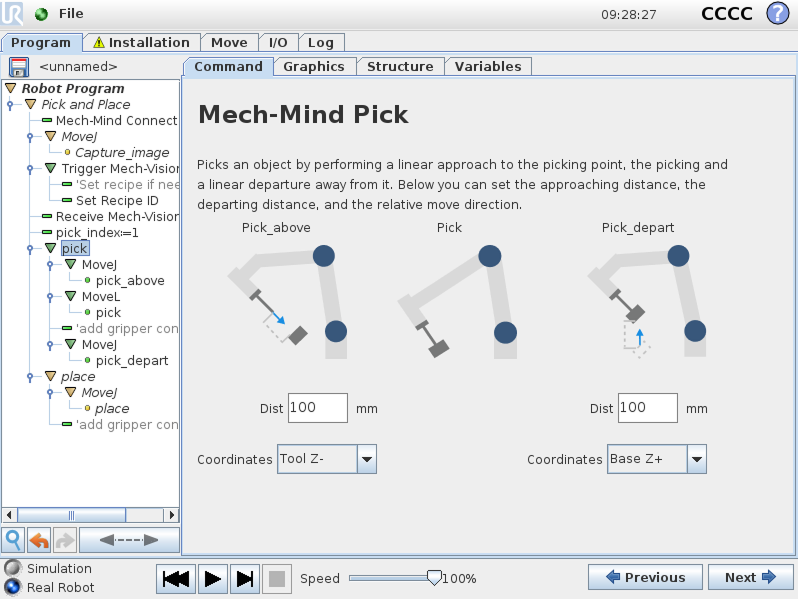
Set the pick task.
A pick task consists of three motions: Pick_above (a linear move to the approach point for picking), Pick (a move to the picking point to pick the object), and Pick_depart (a linear move to depart after picking).
-
Set the parameters Dist and Coordinates for the Pick_above and Pick_depart respectively on the right panel, and then press Next.
-
Keep the default settings for the MoveJ node on the right Move panel, and then press Next.
-
Keep the default settings for the pick_above node on the right Waypoint panel, and then press Next.
-
Keep the default settings for the MoveL node on the right Move panel, and then press Next.
-
Keep the default settings for the pick node on the right Waypoint panel, and then press Next.
-
Add gripper control logic for picking after the pick node according to your actual conditions.
-
Keep the default settings for the MoveJ node on the right Move panel, and then press Next.
-
Keep the default settings for the pick_depart node on the right Waypoint panel, and then press Next.
-
-
Set the place task.
-
Press Next to proceed to the MoveJ node.
-
Keep the default settings for the MoveJ node on the right Move panel, and then press Next.
-
Manually move the robot to the proper location to place the picked object.
-
Go back to the teach pendant, and press Set Waypoint on the right Waypoint panel. You will be switched to the Move tab.
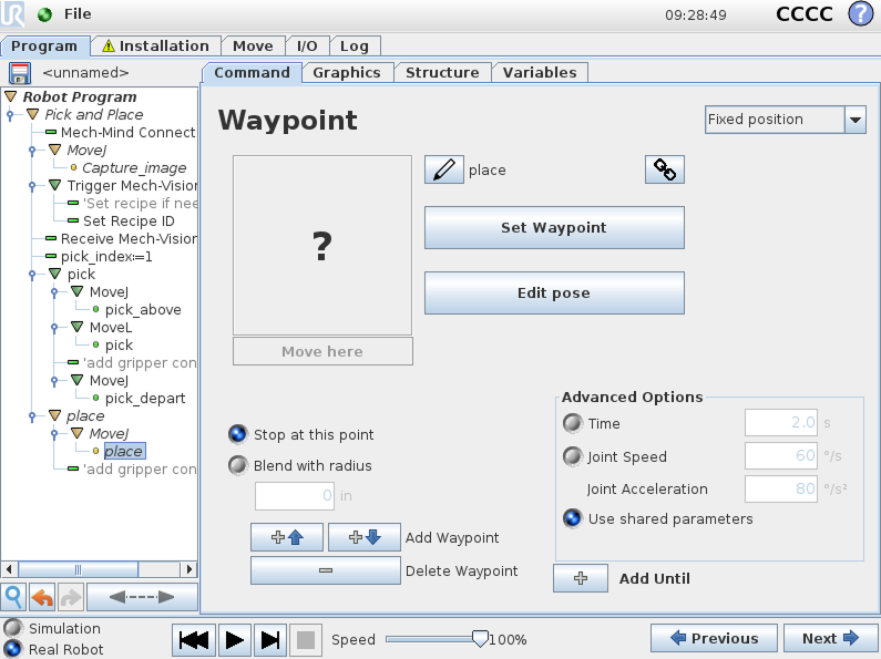
-
On the Move tab, confirm that the robot’s current flange pose is proper and press OK.
-
Once the place pose is set, press Next.
-
Add gripper control logic for placing after the place node in the program tree according to your actual conditions.
-
Till now, a simple pick-and-place program with Mech-Vision (picking points) has been completed. You can run it by pressing ![]() on the bottom bar.
on the bottom bar.
Create a Pick and Place with Mech-Vision (picking path) Program
To create a Pick and Place program with Mech-Vision (picking path), follow these steps:
-
Enable the With Vision (picking path) option.
-
On the UR teach pendant, select .
-
Select , and press Mech-Mind Pick and Place under the URCaps tab. A Pick and Place program node is then added to the Robot Program on the left panel.
-
Select the Command tab, and press the With Vision (picking path) button on the right panel.
-
When you see that a program template is automatically created under the Pick and Place node in the program tree, press Next on the bottom bar.

-
-
Set the value of Host IP to the IP address of the Mech-Mind IPC by referring to step 2 in Pick and Place with Mech-Vision (picking points).
-
Set the image-capturing pose by referring to step 3 in Pick and Place with Mech-Vision (picking points).
-
See how to trigger the Mech-Vision project to run by referring to step 4 in Pick and Place with Mech-Vision (picking points).
-
Set how to receive Mech-Vision result.
Double-click the Receive Mech-Vision Result node, set the Result type and Return pose type, then set the name of the variables for saving returned data. Finally, press Next.
Since the function of this example is to obtain the planned path from Mech-Vision, the Result type here can only be set to Planned path. 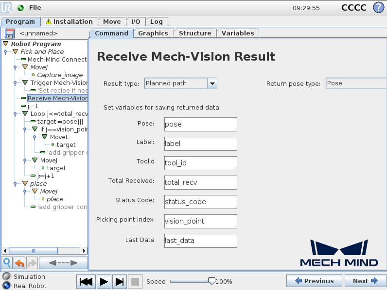
-
When the Result type is set to Planned path, and the Return pose type is set to Pose, it indicates that the received pose type is the TCP. Explanations for other parameters are shown in the table below.
Parameter Description Pose
The pose here refers to the robot’s TCP. By default, the poses are saved in the array variable pose[], with the array starting index as 1.
Label
The label corresponds to each pose. Its value is an integer. By default, labels are saved in the array variable label[], with the array starting index as 1.
ToolId
The tool ID corresponds to the sent pose. ts value is an integer. By default, tool IDs are saved in the array variable label[], with the array starting index as 1.
Total Received
The number of poses received from Mech-Vision. By default, saved in the variable total_recv.
Status Code
The status code returned by Mech-Vision. Codes starting with 11xx indicate normal status, while codes starting with 10xx indicate errors. For detailed information, refer to the Status Codes and Troubleshooting. By default, the status code is saved in the variable status_code.
Pick point index
Indicates the position of the Vision Move waypoint corresponding to the “Vision Move” Step of the path planning tool in the entire path. If the path does not contain a “Vision Move” waypoint, the value of this parameter is 0. By default, the vision point index is saved in the variable vision_point.
For example, if the planned path consists of the following waypoints: "Fixed-Point Move 1", "Fixed-Point Move_2", "Vision Move", "Fixed-Point Move_3", the position of the Vision Move waypoint is 3.
Last Data
Indicates whether all planned path poses have been received from Mech-Vision. The value is either 0 or 1, where 0 means not all poses are received, and 1 means all poses are received. By default, this information is saved in the variable last_data.
-
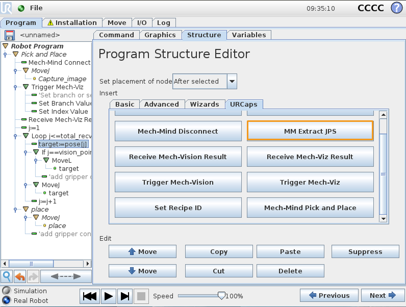
When the Result type is set to Planned path, and the Return pose type is set to Jps, it indicates that the received pose type is the joint position. The explanations for label, toolID, and other parameters are as shown in the table above. By default, the joint position data is saved in the jps[] array variable. Please do not use the jps[] array variable directly; users must extract the array variable before using the joint positions within it. For this example, users can extract the joint positions by following the steps below.
-
Double-click the Receive Mech-Vision Result node and select Jps for the Return pose type.
-
Double-click the target:=pose[j] node, then click , and the Extract Jps node will appear.
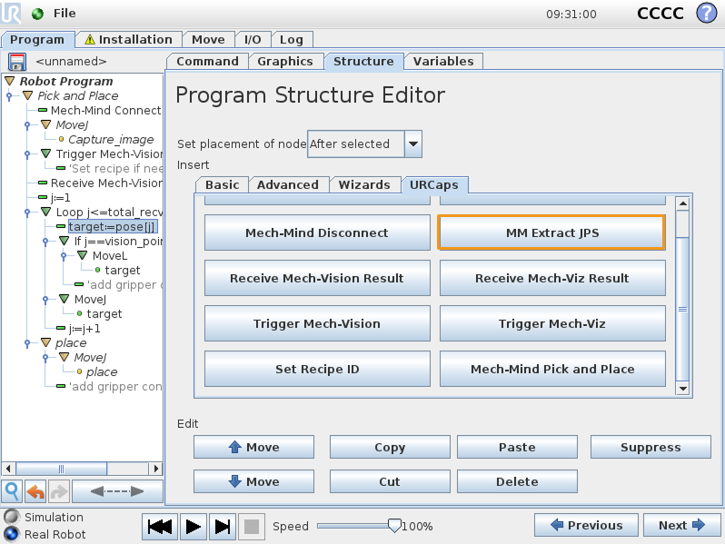
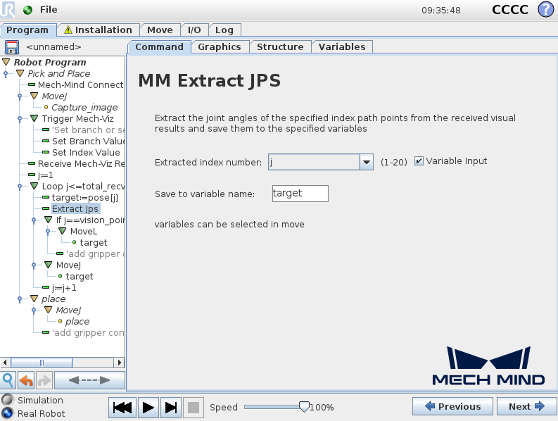
-
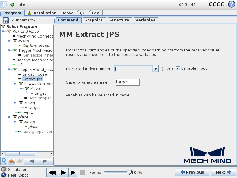
Double-click the Extract Jps node, check Variable Input, select j as the Extracted index number, and finally enter target1 in the Save to variable name field.
-
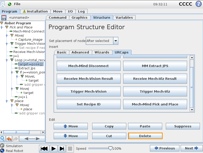
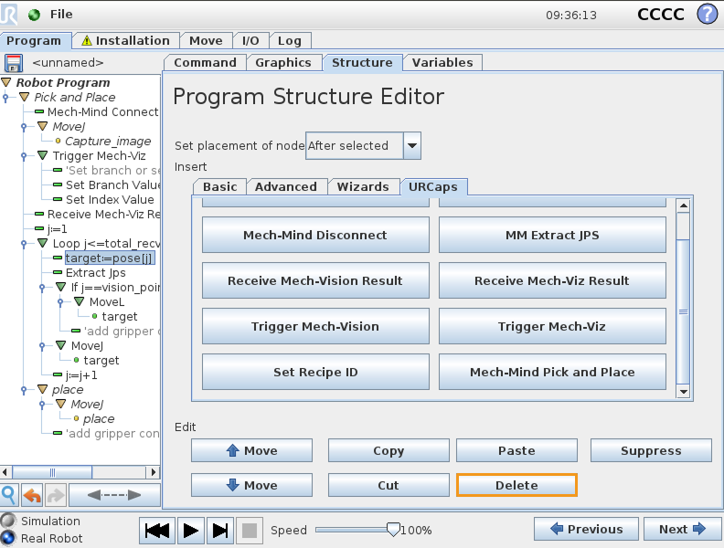
Double-click the target:=pose[j] node, click Structure, and click Delete in the Edit filed.
-
Replace the target variable in the subsequent nodes with the target1 variable.
-
-
-
Configure the motion loop, which drives the robot to follow the path planned by the “Path Planning” Step, that is, approach the object, pick the object, and depart from the picking point (not including placing the object). For how to set MoveL and MoveJ nodes, refer to step 7 in Pick and Place with Mech-Vision (picking points).
-
In actual applications, the motion loop may contain several pick_above MoveJ nodes, a pick MoveL node, and several pick_depart MoveJ nodes.
-
If you change the default variable names of poses, labels, etc. in the node of Receive Mech-Vision Result, you need to change the variables used in this step.
-
-
Set the place task by referring to step 8 in Pick and Place with Mech-Vision (picking points).
Till now, a simple pick-and-place program with Mech-Vision (picking path) has been completed. You can run it by pressing ![]() on the bottom bar.
on the bottom bar.
Create a Pick and Place with Mech-Viz Program
To create a Pick and Place program with Mech-Viz, follow these steps:
-
Enable the With Mech-Viz option.
-
On the UR teach pendant, select .
-
Select , and press Mech-Mind Pick and Place under the URCaps tab. A Pick and Place program node is then added to the Robot Program on the left panel.
-
Select the Command tab, and press the With Mech-Viz option.
-
When you see that a program template is automatically created under the Pick and Place node in the program tree, press Next on the bottom bar.
-
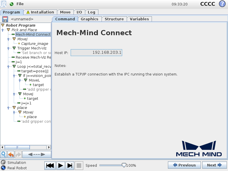
-
At the Mech-Mind Connect node, verify that the Host IP setting is the IP address of the IPC on the right Mech-Mind Connect panel.
-
Set the image-capturing pose by referring to step 3 in Pick and Place with Mech-Vision (picking points).
-
Trigger the Mech-Viz project to run.
-
Set the Type of robot pose to send parameter on the right Trigger Mech-Viz panel. The specific parameter values are explained in the table below.
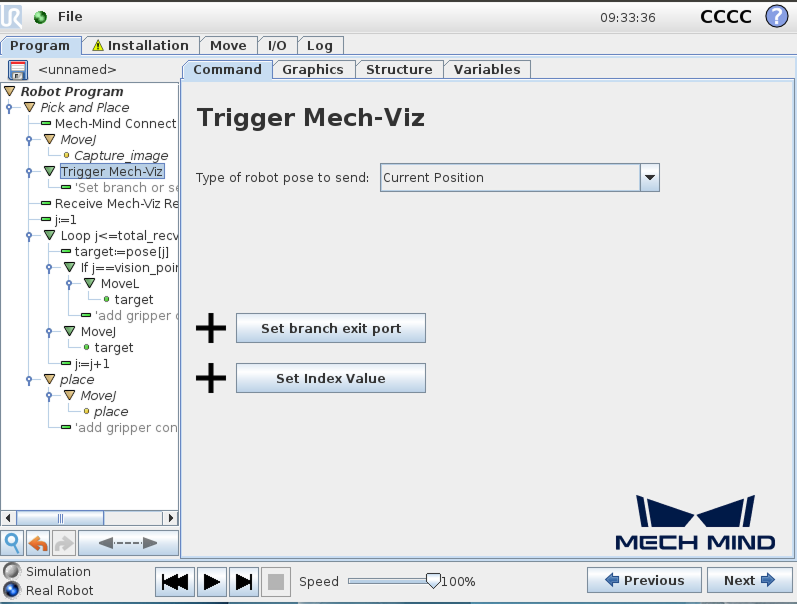
Parameter Description Type of robot pose to send
Specify the type of robot pose to be sent to the Mech-Viz project.
-
Current Position: Send the robot’s current joint positions and flange pose to the Mech-Viz project. This setting should be used when the camera is mounted in eye in hand mode.
-
Predefined JPs: Send the custom joint positions to the Mech-Viz project. This can be used to trigger the Mech-Viz project to plan the next round of paths in advance when the robot is outside the image-capturing area. This parameter should be used when the camera is mounted in Eye-To-Hand mode and a pre-capture image is required.
-
If the Mech-Viz project contains a “Branch by Msg” Step, press Set branch exit port, and proceed to Step b to set the branch exit port.
-
If the Mech-Viz project contains an index-related Step, press Set Index Value, and proceed to Step c to set the index value.
-
-
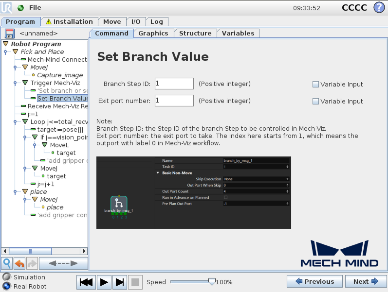
(Optional) Select the Set Branch Value node in the program tree, set Branch Step ID and Exit port number on the right panel, and press Next.
-
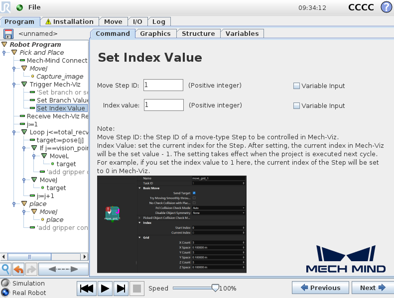
(Optional) Select the Set Index Value node in the program tree, set Move Step ID and Index value on the right panel, and press Next.
-
-
Set how to receive Mech-Viz result.
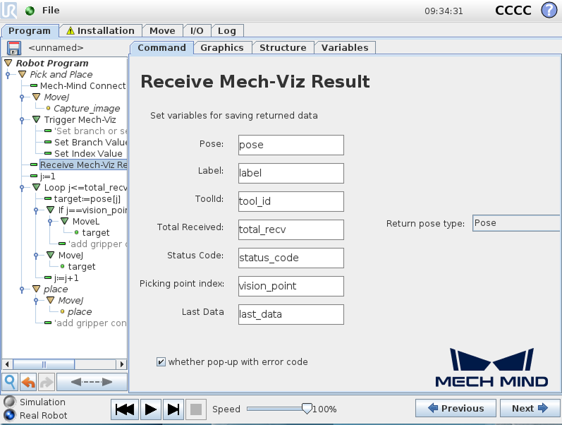
Double-click the Receive Mech-Viz Result node in the program tree, set the variables for saving the Mech-Viz result, and press Next.
-
When the Return pose type is set to Pose, it indicates that the received pose type is the TCP. Explanations for other parameters are shown in the table below.
Parameter Description Pose
The pose here refers to the robot’s TCP. By default, the poses are saved in the array variable pose[], with the array starting index as 1.
Label
The label corresponds to each pose. Its value is an integer. By default, labels are saved in the array variable label[], with the array starting index as 1.
ToolId
The tool ID corresponds to the sent pose. ts value is an integer. By default, tool IDs are saved in the array variable label[], with the array starting index as 1.
Total Received
The number of poses received from Mech-Viz. By default, saved in the variable total_recv.
Status Code
The status code returned by Mech-Vision. Codes starting with 21xx indicate normal status, while codes starting with 20xx indicate errors. For detailed information, refer to the Status Codes and Troubleshooting. By default, the status code is saved in the variable status_code.
Pick point index
Indicates the position of the Vision Move waypoint (i.e., the waypoint corresponding to the “Vision Move” Step in the project) in the planned path. If the path does not contain a “Vision Move” waypoint, the value of this parameter is 0. By default, the vision point index is saved in the variable vision_point.
For example, if the planned path consists of the following waypoints: "Fixed-Point Move 1", "Fixed-Point Move_2", "Vision Move", "Fixed-Point Move_3", the position of the Vision Move waypoint is 3.
Last Data
Indicates whether all planned path poses have been received from Mech-Viz. The value is either 0 or 1, where 0 means not all poses are received, and 1 means all poses are received. By default, this information is saved in the variable last_data.
-
When the Return pose type is set to Jps, it indicates that the received pose type is the JPs. The explanations for label, toolID, and other parameters are as shown in the table above. By default, the joint position data is saved in the jps[] array variable. Please do not use the jps[] array variable directly; users must extract the array variable before using the joint positions within it. For this example, users can extract the joint positions by following the steps below.
-
Double-click the Receive Mech-Viz Result node and select Jps for the Return pose type.
-
Double-click the target:=pose[j] node, then click , and the Extract Jps node will appear.
-
Double-click the Extract Jps node, check Variable Input, select j as the Extracted index number, and finally enter target1 in the Save to variable name field.
-
Double-click the target:=pose[j] node, click Structure, and click Delete in the Edit filed.
-
Replace the target variable in the subsequent nodes with the target1 variable.
-
-
-
Configure the motion loop, which drives the robot to follow the path planned by Mech-Viz, that is, approach the object, pick the object, and depart from the picking point (not including placing the object). For how to set MoveL and MoveJ nodes, refer to step 7 in Pick and Place with Mech-Vision (picking points).
-
In actual applications, the motion loop may contain several pick_above MoveJ nodes, a pick MoveL node, and several pick_depart MoveJ nodes.
-
If you change the default variable names of poses, labels, etc. in the node of Receive Mech-Viz Result, you need to change the variables used in this step.
-
-
Set the place task by referring to step 8 in Pick and Place with Mech-Vision (picking points).
Till now, a simple pick-and-place program with Mech-Viz has been completed. You can run it by pressing ![]() on the bottom bar.
on the bottom bar.