IO not linked to a hardware input-output..mm_control-
Problem
When running the main control program on the STAUBLI robot, the following error occurs:
VAL 3 runtime error. IO not linked to a hardware input-output..mm_control-.
Possible Causes
The following two reasons may cause the above error.
-
Incorrect IO board settings.
-
Incorrect SIO settings.
Solutions
| If the IO settings remain incorrect, you may consider removing all IO-related content from the program and only controlling the robot’s movements without using IO. |
-
Cause 1:
-
If the robot is not connected to the Term_1_(D24403000) EtherCat IO board, delete the IO-related code in the mm_control.dtx file, specifically the following code.
The files mm_control.dtx and statusServer.pgx are located at the path Communication Component/Robot_Server/Robot_FullControl/staubli/mm_controlunder the installation directory of Mech-Vision and Mech-Viz.<Data name="exDO" access="private" xsi:type="array" type="dio" size="4"> <Value key="0" link="J206_EtherCAT\Term_1_(D24403000)\%Q0" /> <Value key="1" link="J206_EtherCAT\Term_1_(D24403000)\%Q1" /> <Value key="2" link="J206_EtherCAT\Term_1_(D24403000)\%Q2" /> <Value key="3" link="J206_EtherCAT\Term_1_(D24403000)\%Q3" /> </Data> <Data name="exDI" access="private" xsi:type="array" type="dio" size="8"> <Value key="0" link="J206_EtherCAT\Term_1_(D24403000)\%I0" /> <Value key="1" link="J206_EtherCAT\Term_1_(D24403000)\%I1" /> <Value key="2" link="J206_EtherCAT\Term_1_(D24403000)\%I2" /> <Value key="3" link="J206_EtherCAT\Term_1_(D24403000)\%I3" /> <Value key="4" link="J206_EtherCAT\Term_1_(D24403000)\%I4" /> <Value key="5" link="J206_EtherCAT\Term_1_(D24403000)\%I5" /> <Value key="6" link="J206_EtherCAT\Term_1_(D24403000)\%I6" /> <Value key="7" link="J206_EtherCAT\Term_1_(D24403000)\%I7" /> </Data>At the same time, modify the values of statusNum[7] and statusNum[8] in the statusServer.pgx file. The following code shows the updated values.
statusNum[7]=0 statusNum[8]=0 -
If the robot uses a different model of IO board, please configure it according to the official robot manual. Ensure the IO board is functioning properly. Then, modify the exDO and exDI link information in the mm_control.dtx file according to the actual IO device names.
    <Data name="exDO" access="private" xsi:type="array" type="dio" size="4">
      <Value key="0" link="J206_EtherCAT\Term_1_(D24403000)\%Q0" />
      <Value key="1" link="J206_EtherCAT\Term_1_(D24403000)\%Q1" />
      <Value key="2" link="J206_EtherCAT\Term_1_(D24403000)\%Q2" />
      <Value key="3" link="J206_EtherCAT\Term_1_(D24403000)\%Q3" />
    </Data>
    <Data name="exDI" access="private" xsi:type="array" type="dio" size="8">
      <Value key="0" link="J206_EtherCAT\Term_1_(D24403000)\%I0" />
      <Value key="1" link="J206_EtherCAT\Term_1_(D24403000)\%I1" />
      <Value key="2" link="J206_EtherCAT\Term_1_(D24403000)\%I2" />
      <Value key="3" link="J206_EtherCAT\Term_1_(D24403000)\%I3" />
      <Value key="4" link="J206_EtherCAT\Term_1_(D24403000)\%I4" />
      <Value key="5" link="J206_EtherCAT\Term_1_(D24403000)\%I5" />
      <Value key="6" link="J206_EtherCAT\Term_1_(D24403000)\%I6" />
      <Value key="7" link="J206_EtherCAT\Term_1_(D24403000)\%I7" />
    </Data>
-
-
Cause 2:
Check the SIO settings by following these steps.
-
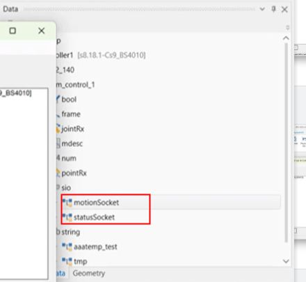
In the SRS (Staubli Robotics Suite) software, open the project’s Data list and check whether the motionsocket and statussocket variables exist under the sio node. If they do not exist, please add them manually. Steps: Double-click sio. In the pop-up window, select the type and enter the variable name.
-
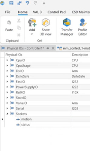
Open the Physical IOs interface and check whether motion and status exist under the Sockets node. If they do not exist, please add them manually. Steps: Right-click the Sockets node and select the edit board button to open the dialog box. Then, click the dropdown menu next to the + icon and select TCP/IP Server. Add motion and status in sequence. The port number for motion should be set to 1111, and for status, it should be 2222.
-
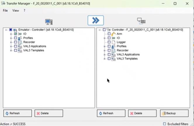
Import the IO settings to the controller by using the transfer manager.
-
Restart the controller.
-