Communication Configuration and Example Program Usage
This section provides instructions on setting up Standard Interface communication via Modbus TCP between an Inovance H5U or EASY Series PLC (with built-in Ethernet module) and the Mech-Mind Vision System.
Hardware and Software Requirements
|
The models and versions listed below are tested and can be used. For other models and versions, you may refer to this guide for operation. If any issues occur, please contact Mech-Mind Technical Support. |
Hardware
-
Inovance H5U or EASY Series PLC: Built-in Ethernet module
The PLC model used in this example is EASY320.
-
Power adapter: 220V AC to 24V DC
-
An IPC and a computer
-
Ethernet cable (used to connect the IPC and the PLC)
Software
| Software | Description | Installed Location |
|---|---|---|
AutoShop V4.8.2.4 |
Inovance PLC software |
Computer that is used for Inovance PLC programming |
Mech-Vision and Mech-Viz |
Mech-Mind Vision System |
IPC |
Apart from the above software, copy the following example files to the computer where AutoShop is installed. The example files are stored in Communication Component/Robot_Interface/Modbus TCP/Inovance H5U&Easy in the installation directory where Mech-Vision and Mech-Viz are installed.
-
Modbus_TCP_Configuration.xls: used to establish communication via Modbus TCP/IP.
-
MM_Modbus_TCP_Interface_Program-v1.0.fe: used to implement the functions of various interface commands.
-
MM_Modbus_TCP_Interface.csv and Camera_User.csv: used to import the structures required by the example programs.
-
Variable_Table.csv: used to import the variables required by the example programs.
| The firewall on the IPC must be turned off. |
Configure IPC and Initiate Communication
Set IP Address of the IPC
-
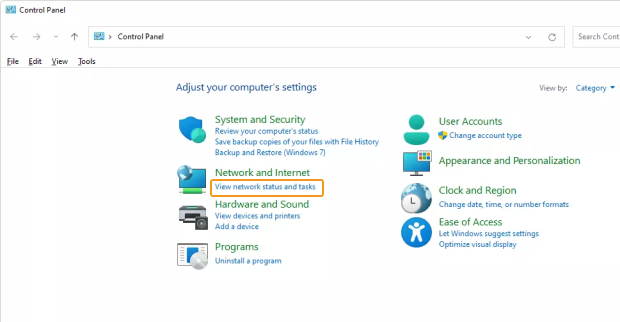
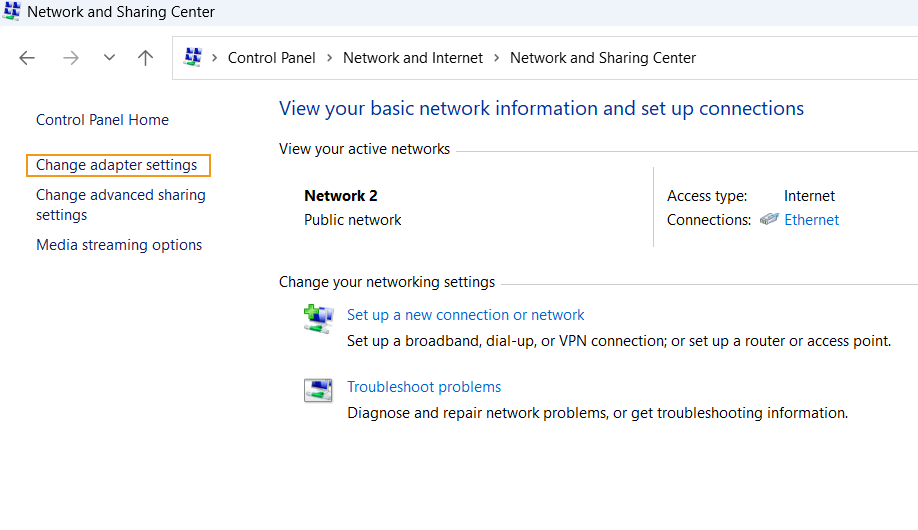
Open the Control Panel, and click View network status and tasks.
-
In the “Network and Sharing Center” window, click Change adapter settings.
-
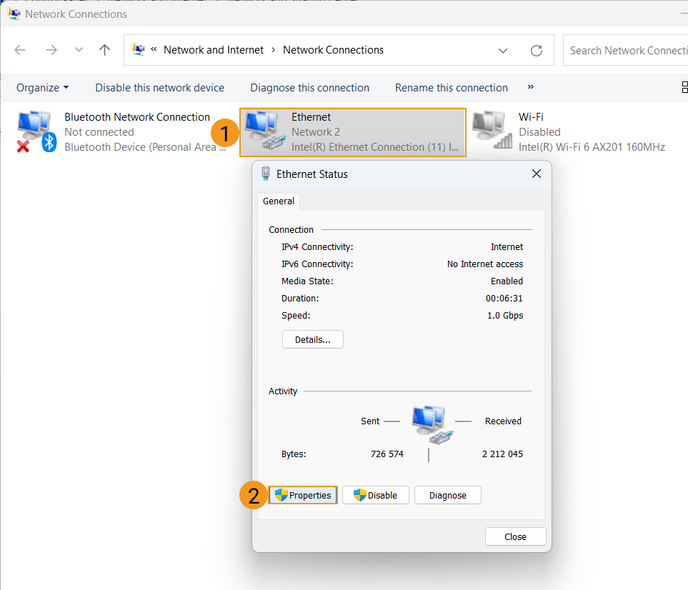
In the “Network Connections” window, double-click the Ethernet interface connected to the PLC, and select Properties in the pop-up Ethernet Status window.
-
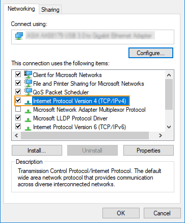
In the Ethernet Properties window, select Networking in the menu bar, and double-click Internet Protocol Version 4(TCP/IPv4).
-
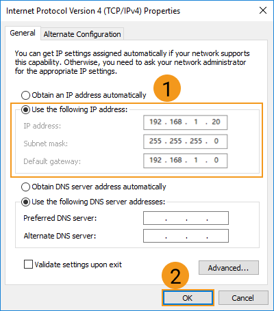
In the Internet Protocol Version 4 (TCP/IPv4) window, select “Use the following IP address”, and set the IP address, subnet mask and default gateway (must be in the same subnet as the PLC). Then, click “OK” to save the changes.
Set up Robot Communication Configuration
-
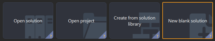
Open Mech-Vision, and you may enter different interfaces. Create a new solution according to the instructions below.
-
If you have entered the Welcome interface, click New blank solution.
-
If you have entered the main interface, click on the menu bar.
-
-
Click Robot Communication Configuration on the toolbar of Mech-Vision.
-
In the Robot Communication Configuration window, complete the following configurations.
-
Click the Select robot dropdown, and choose either Listed robot or Custom robot according to the robot used in your project. Then click Next.
-
Listed robot: Suitable for most robots. Click Select robot model to choose the specific robot model.
-
Custom robot: Suitable for gantry robots or robots not included in the listed robot category. Robot Euler angle convention and robot coordinate system need to be selected.
-
-
In the Communication mode area, select Standard Interface for Interface service type, MODBUS TCP Slave for Protocol, and CDAB for Byte order. Set the Slave ID to 255.
-
Set the port number to 2000 for the host IP address.
-
(Optional) Select Auto enable interface service when opening the solution.
-
Click Apply.

-
-
On the main interface of Mech-Vision, make sure that the Robot Communication Configuration switch on the toolbar is flipped and turned to blue.

Create and Configure the PLC Project
Create a PLC Project
-
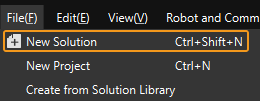
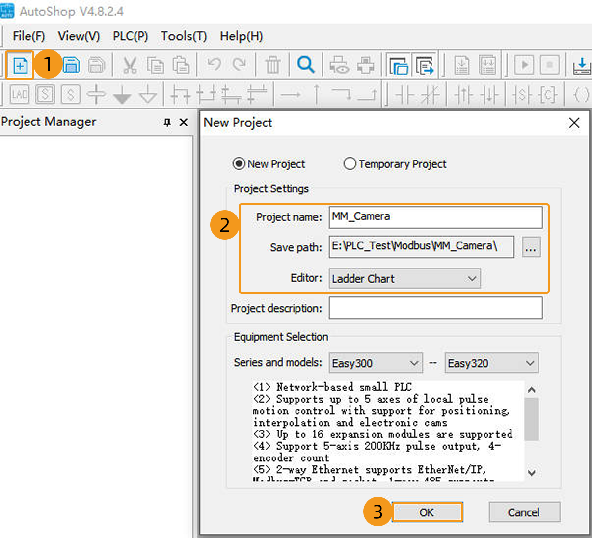
Open AutoShop, and click New Project on the toolbar. Enter the project name in the New Project window, and then select the save path. Select Ladder Chart in the drop-down menu of Editor. Click OK.
-
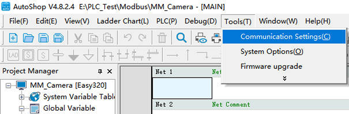
Click in the menu bar.
-
In the following window, select Ethernet for Communication type, and enter the IP address (in this example, 192.168.1.22 is used) of the PLC in the Device IP field. Click Test.
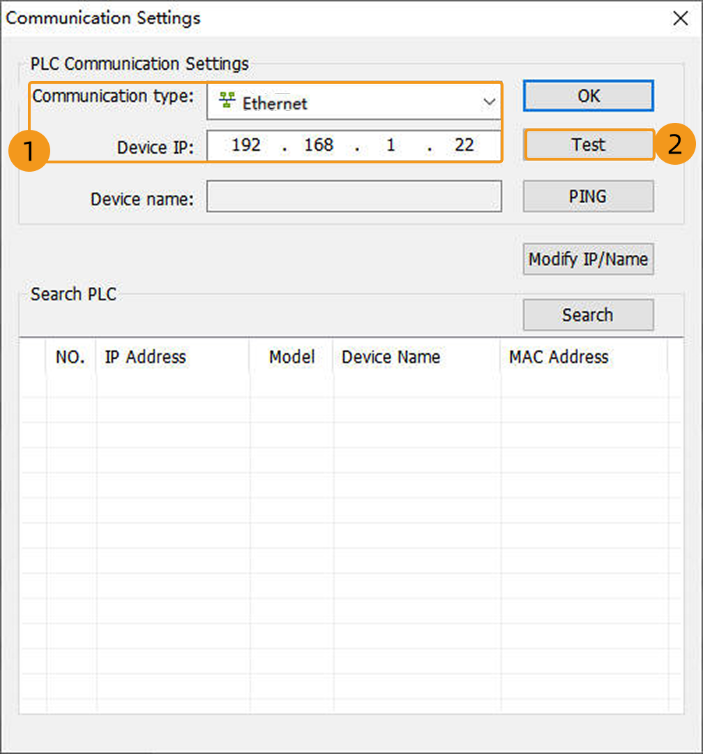
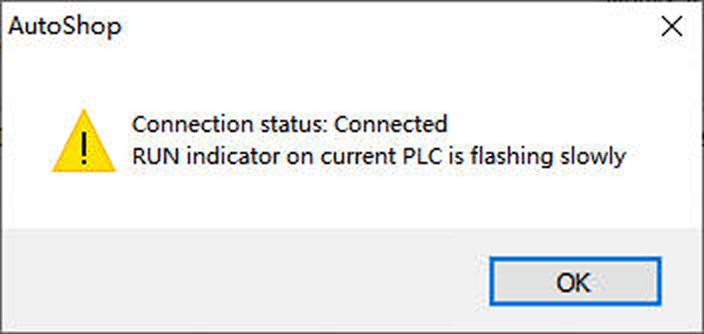
If the connection status shows Connected, it indicates that AutoShop has successfully communicated with the hardware PLC. Then click OK to return to the AutoShop software window.
Configure Communication Parameters of Modbus TCP
-
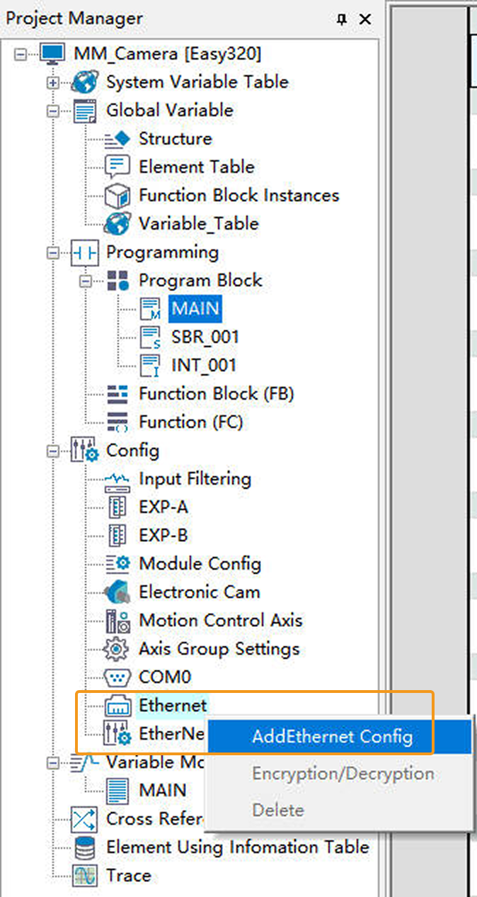
In the Project Manager panel on the left, navigate to Ethernet, right-click Ethernet, and select Add Ethernet Config.
-
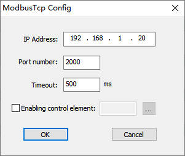
In the following window, enter the IP address of the IPC in the IP Address field (it must be in the same subnet as the PLC device; in this example, 192.168.1.20 is used). Enter the service port number of the IPC in the Port Number field (it must match the host port number set in Mech-Vision; in this example, 2000 is used). Keep the other options at their default settings, and click OK.
-
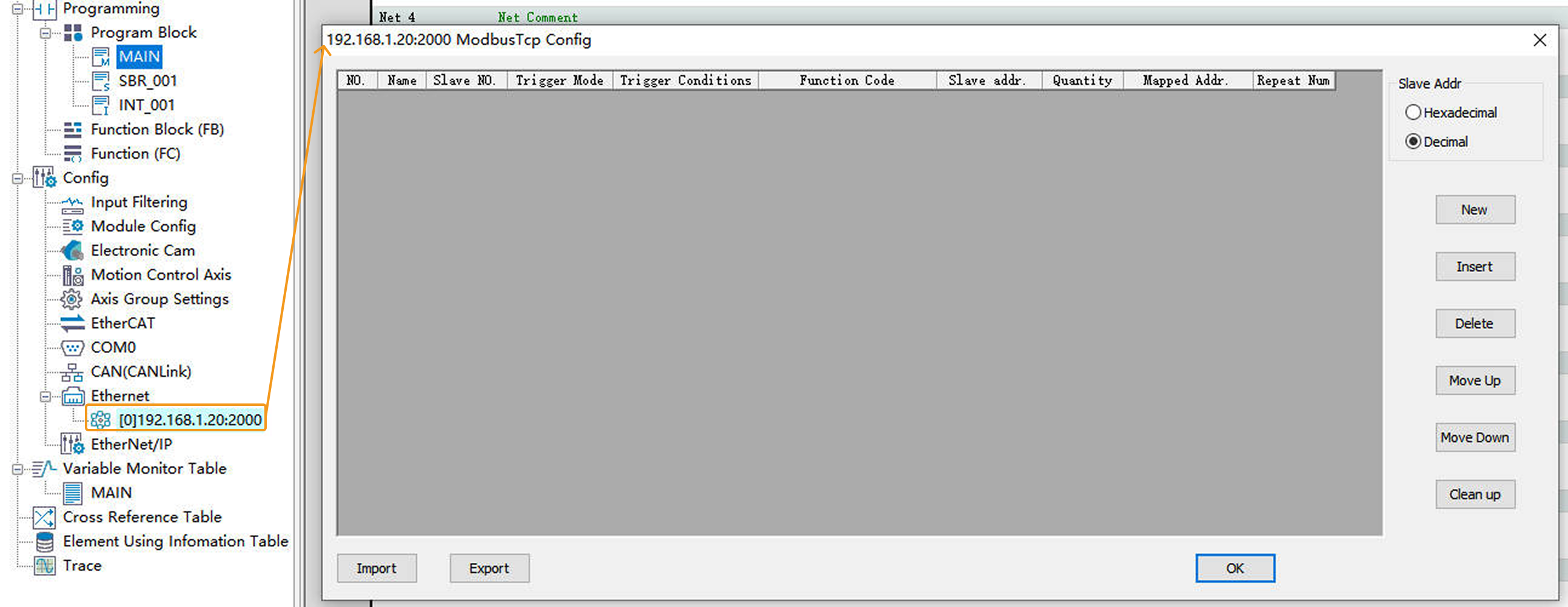
Double-click the newly added Ethernet configuration to open the ModbusTcp Config window.
-
In the following window, click Import, locate and select the Modbus_TCP_Configuration.xls file, then click Open.
The Modbus_TCP_Configuration.xls file is stored in Communication Component/Robot_Interface/Modbus TCP/Inovance H5U&Easyin the installation directory where Mech-Vision and Mech-Viz are installed. User should copy this file from the IPC to the computer where AutoShop is installed in advance.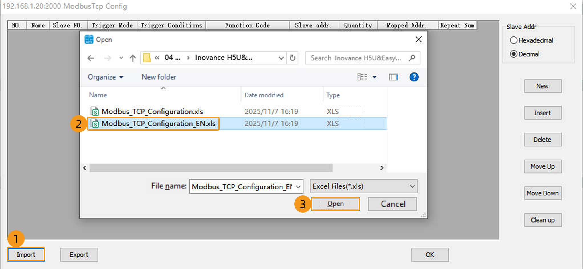
If the file opens successfully, a pop-up message Import data successful! will appear. Finally, click OK to return to the AutoShop software window.
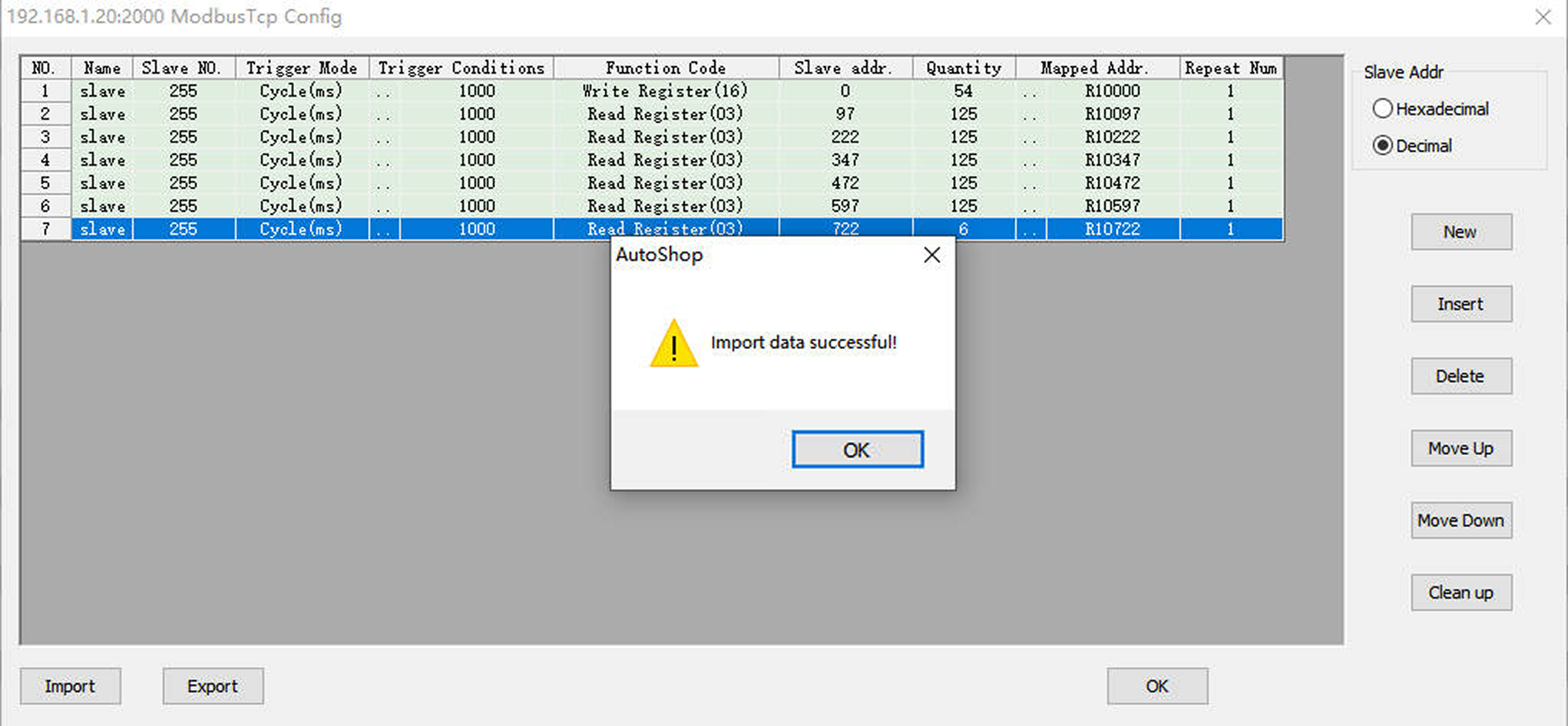
In the figure above, the Slave NO. should be consistent with the slave device address set in Mech-Vision. In this example, the slave register addresses (reserved) are not read.
Import Example Programs
| Before you add an example program to a project already in use, it is recommended to import it to a new project and test it first. |
-
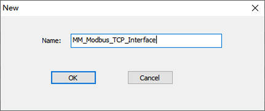
In the Project Manager panel on the left, right-click Structure, and select New Data Structure.
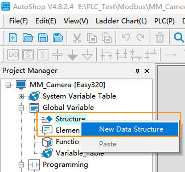
In the following window, enter MM_Modbus_TCP_Interface in the Name field, and click OK. The structure table will open automatically.
-
In the MM_Modbus_TCP_Interface structure table, right-click Import.
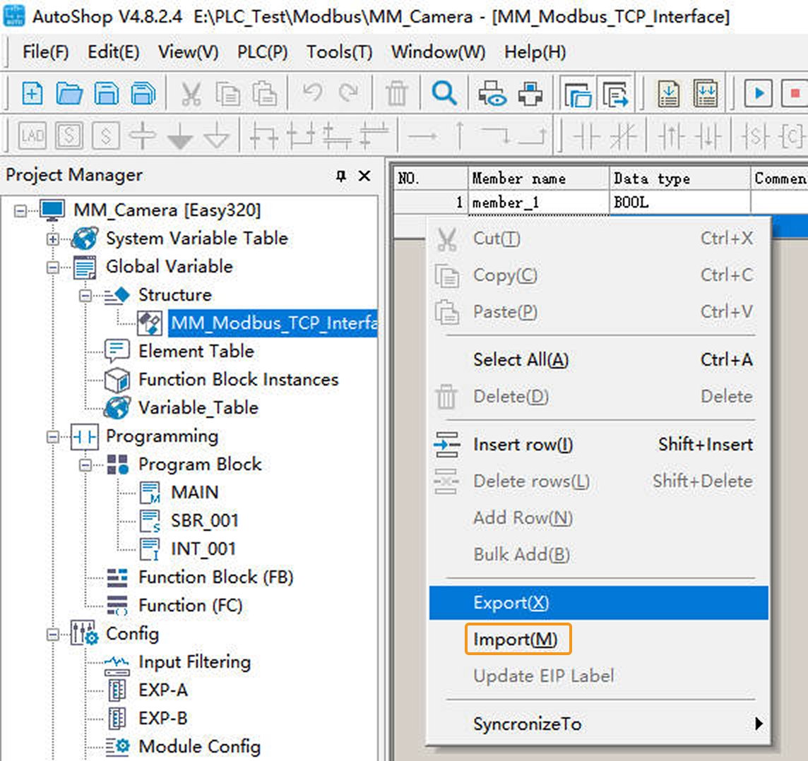
Locate and select the MM_Modbus_TCP_Interface.csv file, and then click Open. If the file opens successfully, a pop-up message Import data successful! will appear. Finally, click OK to return to the AutoShop software window.
The MM_Modbus_TCP_Interface.csv file is stored in Communication Component/Robot_Interface/Modbus TCP/Inovance H5U&Easyin the installation directory where Mech-Vision and Mech-Viz are installed. User should copy this file from the IPC to the computer where AutoShop is installed in advance.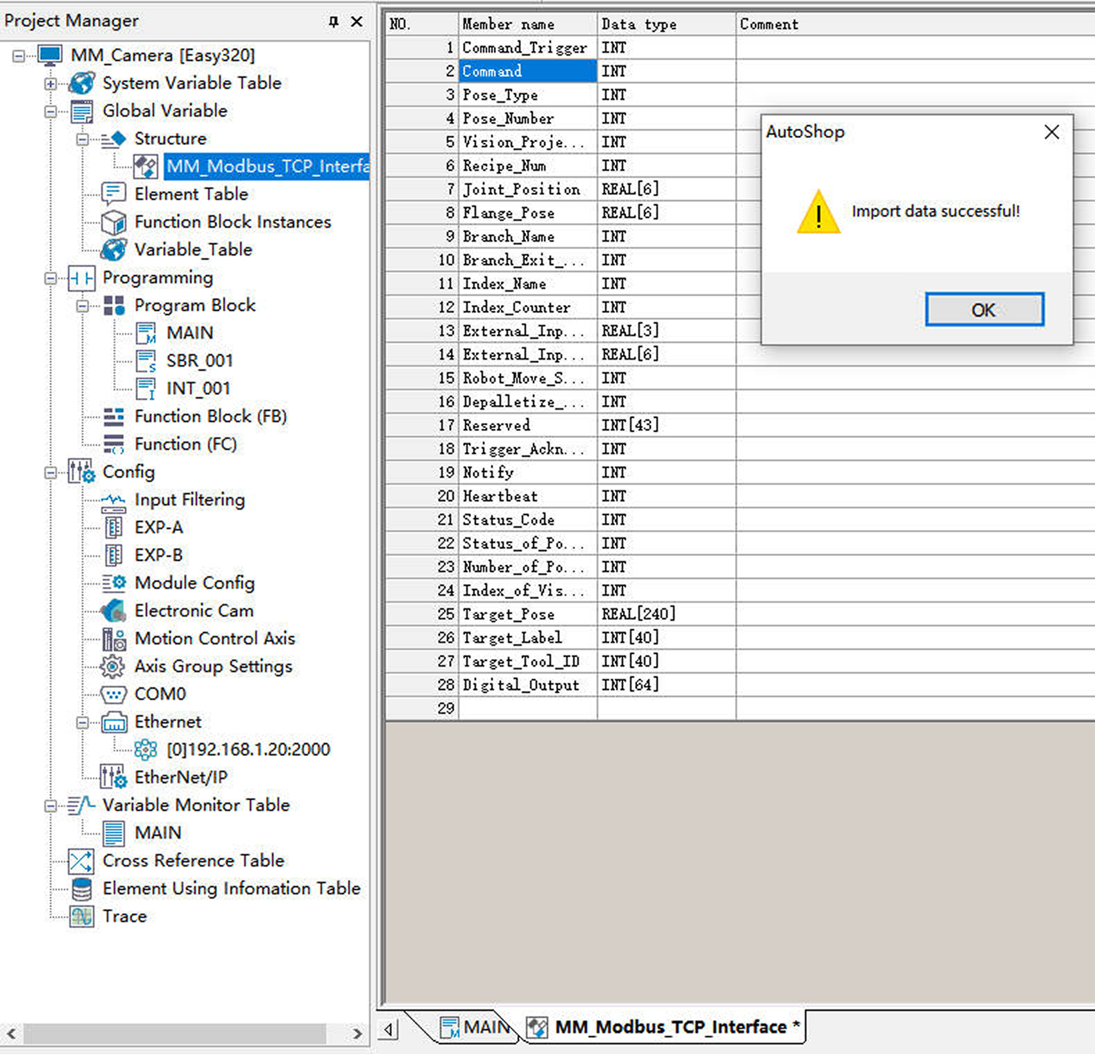
-
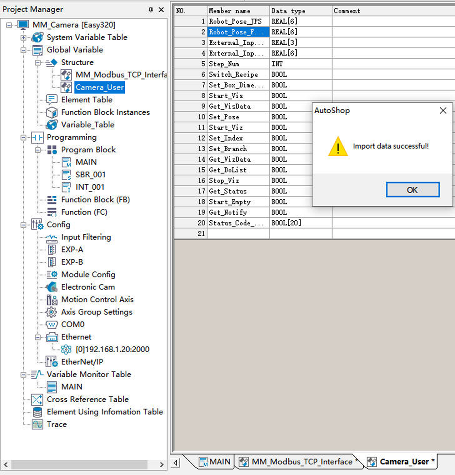
Repeat steps 1 and 2 above to create a new structure named Camera_User and import its member variable data.
-
In the Project Manager panel, right-click Variable_Table and select Open.
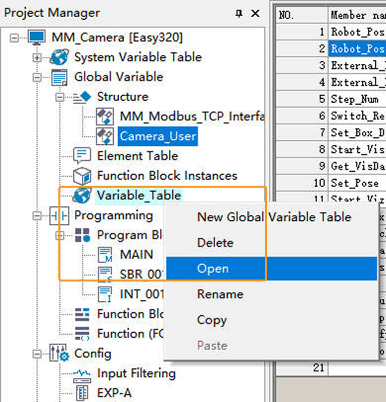
-
In the variable table, right-click Import.
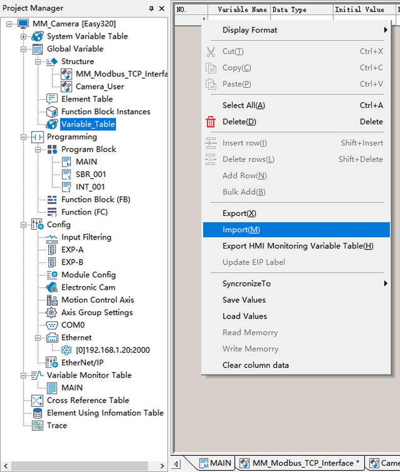
Locate and select the Variable_Table.csv file, then click Open.
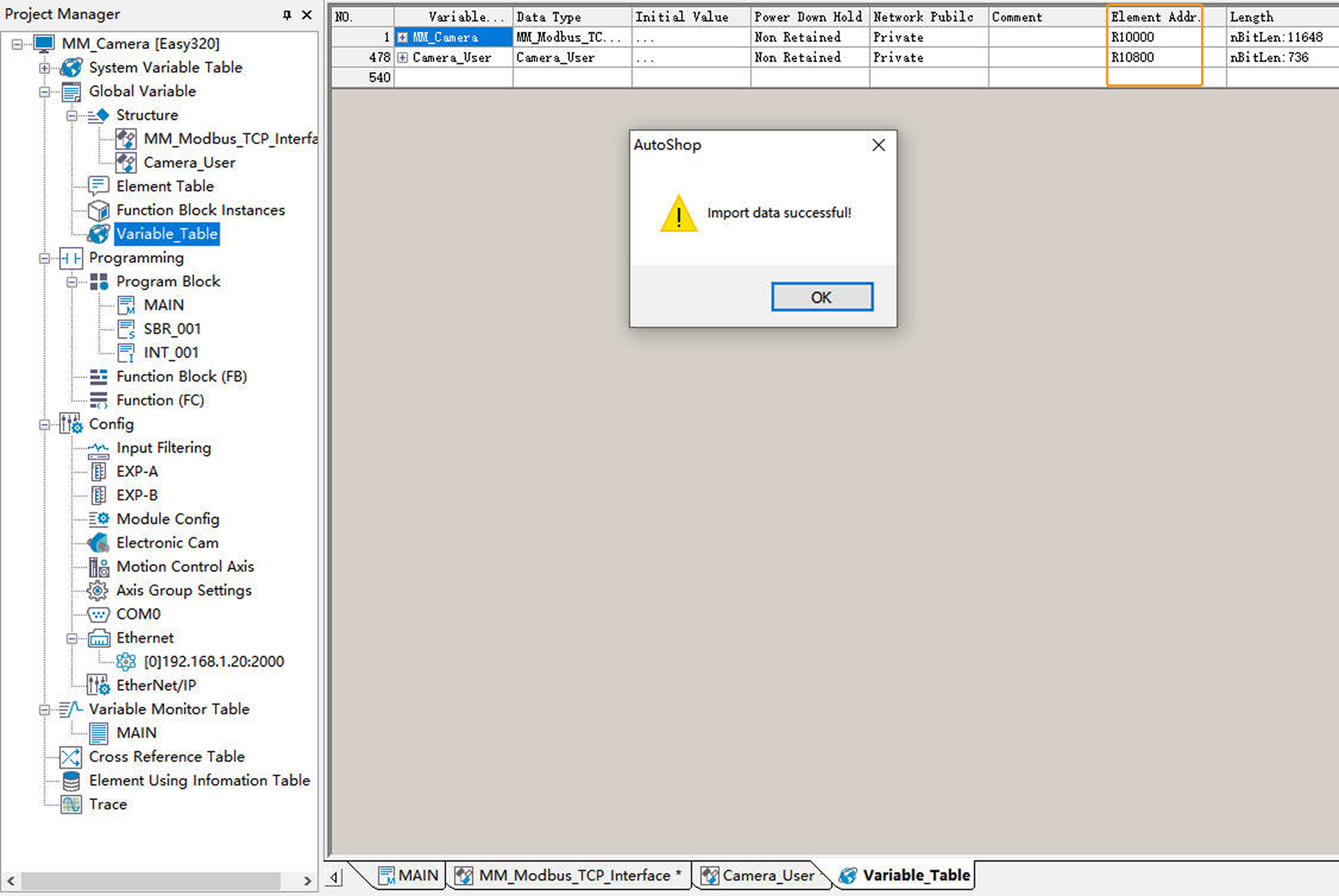
The Variable_Table.csv file is stored in Communication Component/Robot_Interface/Modbus TCP/Inovance H5U&Easyin the installation directory where Mech-Vision and Mech-Viz are installed. User should copy this file from the IPC to the computer where AutoShop is installed in advance.If the file opens successfully, a pop-up message Import data successful! will appear. The Element Addr. here should match the Mapped Addr. in the ModbusTcp Config window from the previous section. Finally, click OK to return to the AutoShop software window.
-
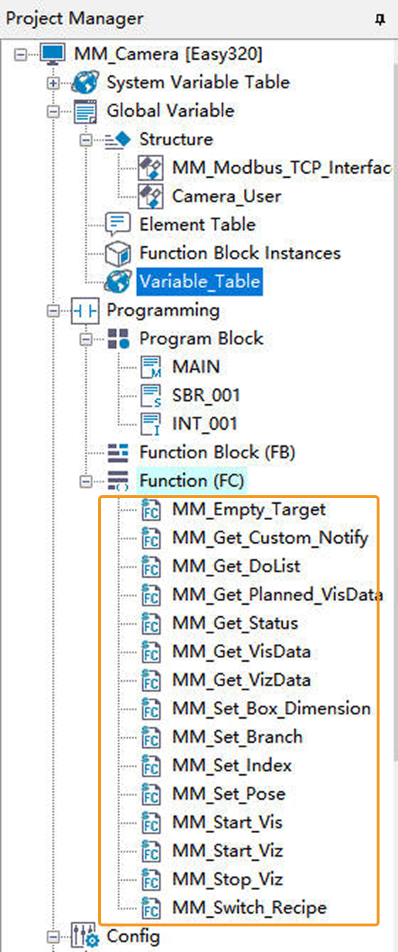
In the Project Manager panel, right-click Function (FC) and select Import FC. Locate and select the MM_Modbus_TCP_Interface_Program-v1.0.fe file, then click Open.
The MM_Modbus_TCP_Interface_Program-v1.0.fe file is stored in Communication Component/Robot_Interface/Modbus TCP/Inovance H5U&Easyin the installation directory where Mech-Vision and Mech-Viz are installed. User should copy this file from the IPC to the computer where AutoShop is installed in advance.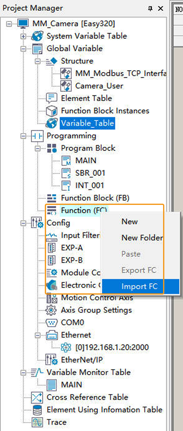
The successfully imported function is shown in the figure below.
Download Communication Configuration and Example Programs to PLC
-
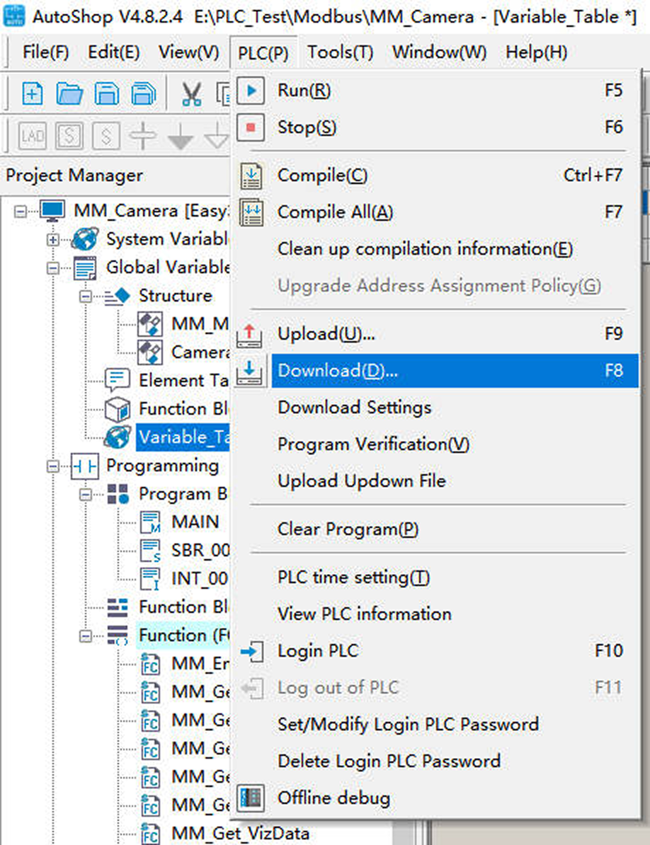
In the menu bar of the AutoShop software window, click .
-
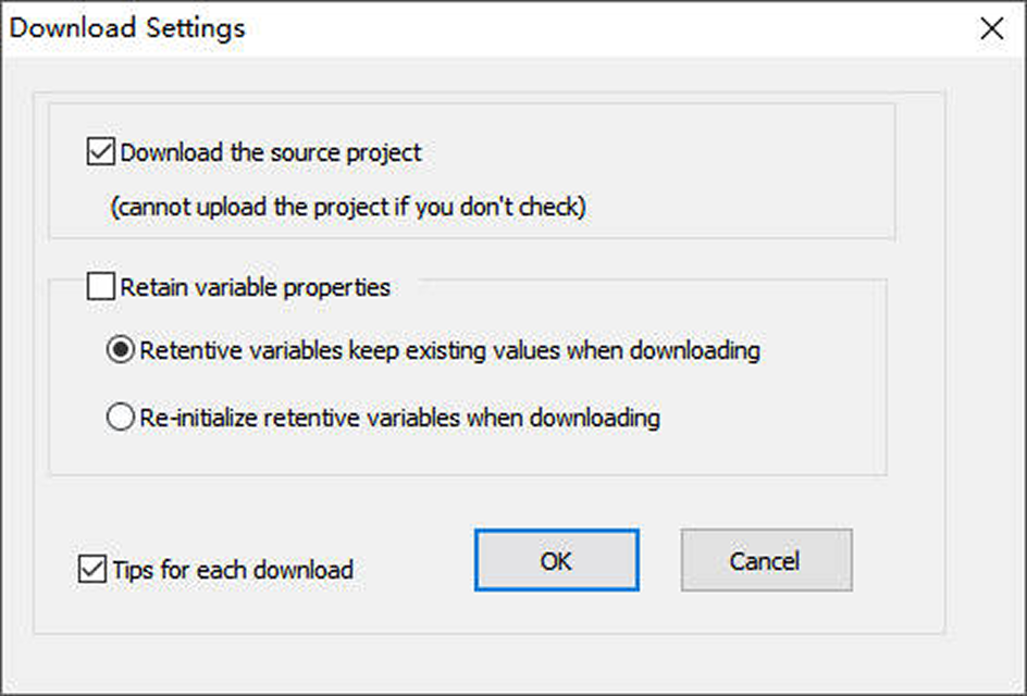
In the following dialog box, keep the default settings and then click OK.
-
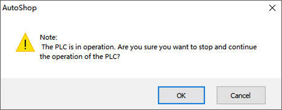
In the following dialog box, click OK.
-
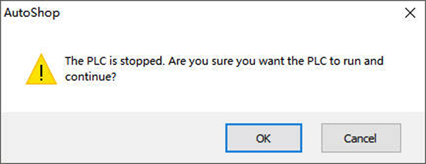
After the project is successfully downloaded, the following dialog box will appear. Once you have verified safety, click OK.
Check Communication
-
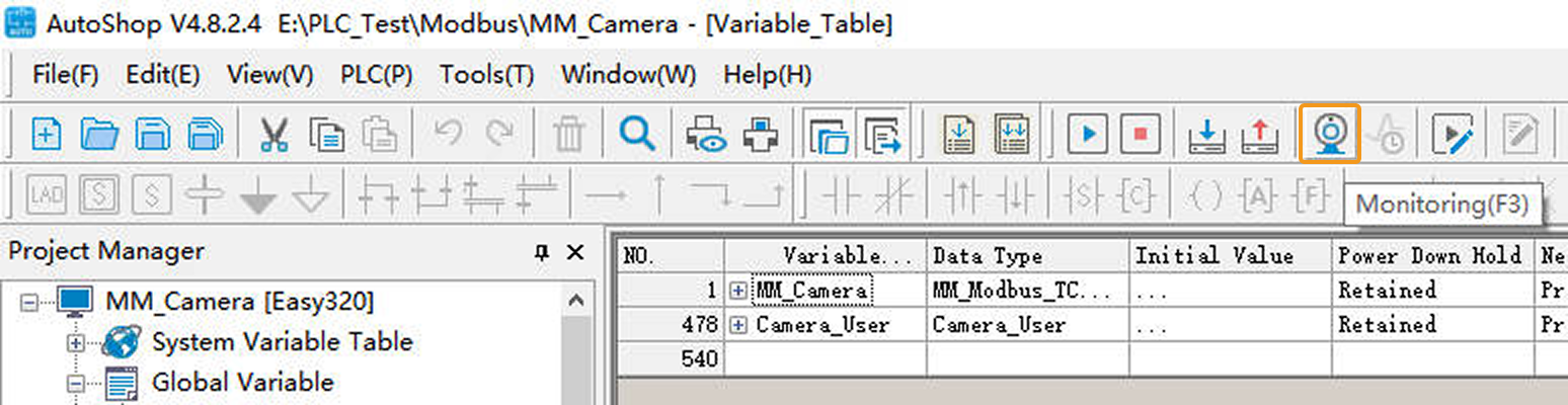
In the AutoShop software toolbar, click the Monitoring icon. In the pop-up dialog box, click Yes.
-
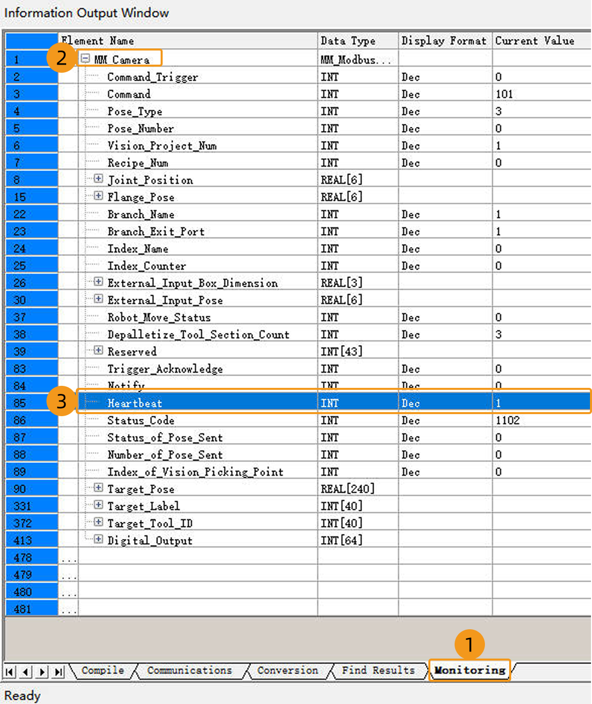
In the following window, click the Monitoring tab and add the MM_Camera variable. If the connection is established successfully, the current value of Heartbeat will keep changing.
-
If the connection is successful, a message indicating a successful connection to the Modbus TCP slave will appear in the Console tab of the log panel in the Mech-Vision main window.
If you don’t see this log message, please check if:
-
The hardware network connection is normal.
-
The Robot Communication Configuration option on the toolbar of Mech-Vision is enabled.
-
The PLC program is downloaded to the PLC.
-
Test with Mech-Vision/Mech-Viz Project
This section introduces how to use the example program FB to trigger the Mech-Vision project to run and obtain the vision result and trigger the Mech-Viz project to run and obtain the planned path.
Preparation
-
Return to Mech-Vision and create a Mech-Vision project. In the Project List section of Mech-Vision, right-click the solution and select Autoload Solution. Projects in the solution are also autoloaded. Meanwhile, the project ID will show up before each project name.
-
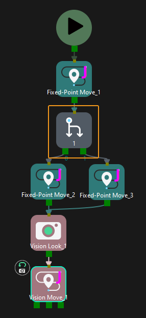
Create a Mech-Viz project. Right-click the project name in the project resource panel in Mech-Viz and select Autoload Project. The Mech-Viz project used for testing should contain a “Branch by Msg” Step that has been renamed to 1 as shown below.
Get Vision Result from Mech-Vision
Parameter Settings
-
In the AutoShop software toolbar, click the Online Modification icon.
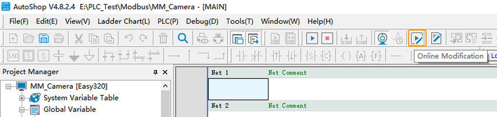
-
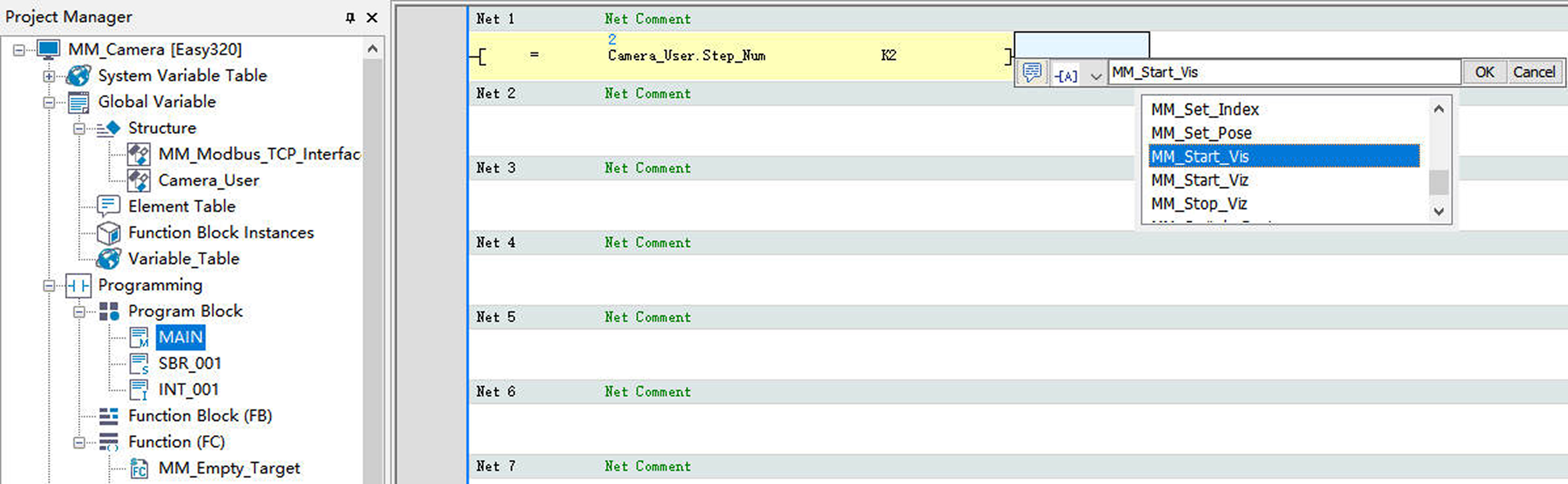
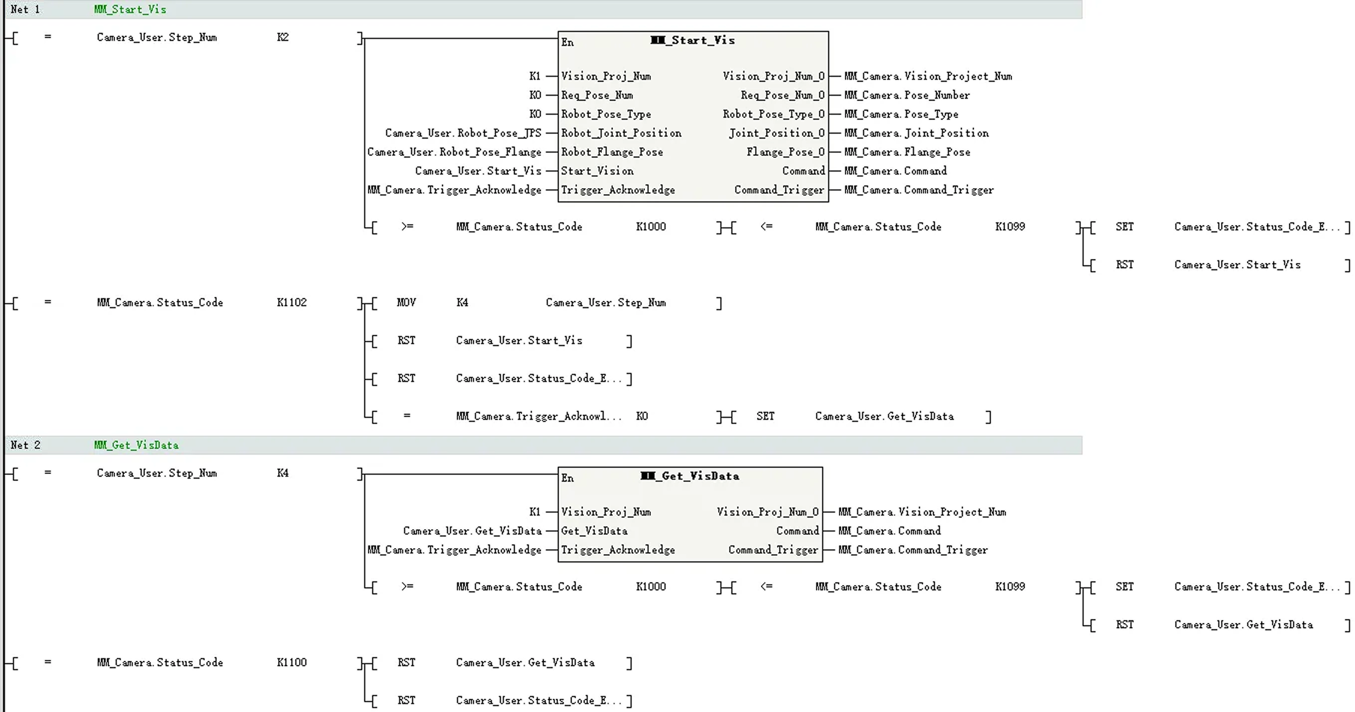
In the Project Manager panel, double-click MAIN. In Net 1, enter the comparison command LD= Camera_User.Step_Num K2. Then apply the command MM_Start_Vis.
-
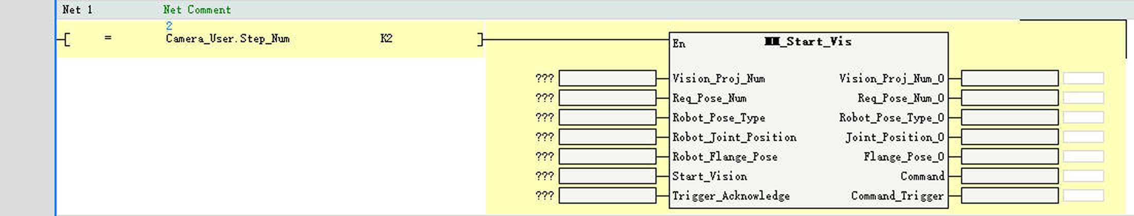
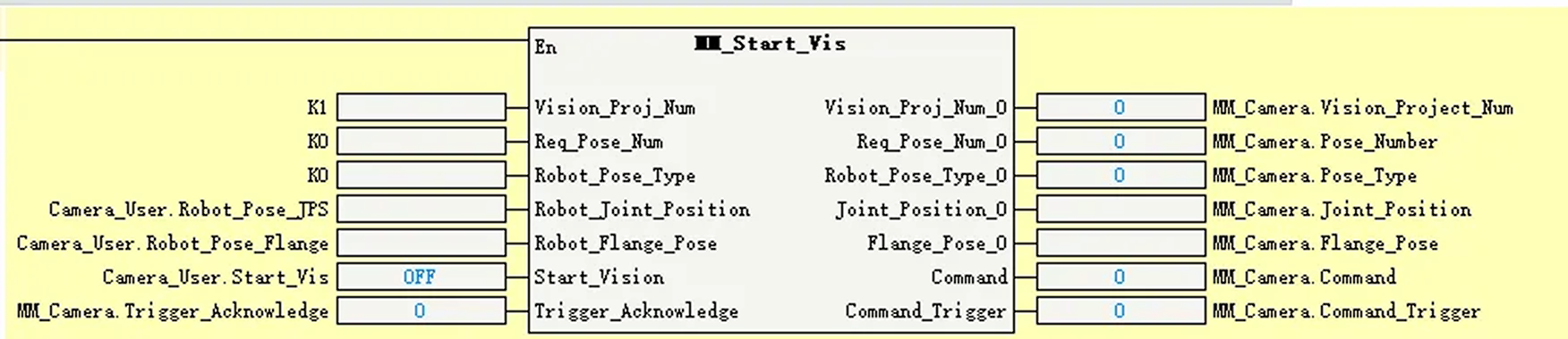
Set the input and output ports of MM_Start_Vis as shown in the figure below.
-
Set the value of Vision_Proj_Num to 1. Then, project No.1 in Mech-Vision will be started.
-
Set the value of Req_Pose_Num to 0. Then, Mech-Vision will return all vision points.
-
Set the value of Robot_Pose_Type to 0. Then, the image-capturing pose does not need to be sent to the Mech-Vision project. For example, the image-capturing pose does not need to be sent when the camera is mounted in eye-to-hand mode.
-
Add the corresponding variables to the remaining ports as shown in the figure below.
-
-
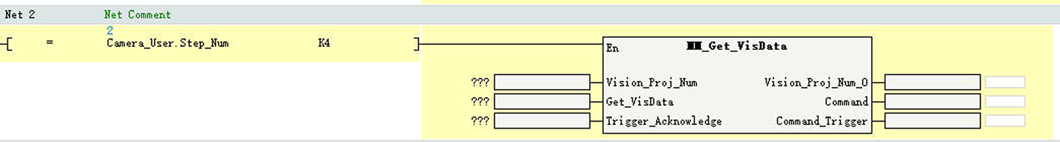
In Net 2, enter the comparison command LD= Camera_User.Step_Num K4. Then apply the command MM_Get_VisData.
-
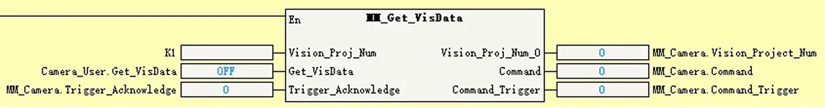
Set the input and output ports of MM_Get_VisData as shown in the figure below.
-
Set the Vision_Proj_Num port value to 1, indicating that the vision results of Mech-Vision project 1 will be retrieved.
-
Add the corresponding variables to the remaining ports as shown in the figure below.
-
-
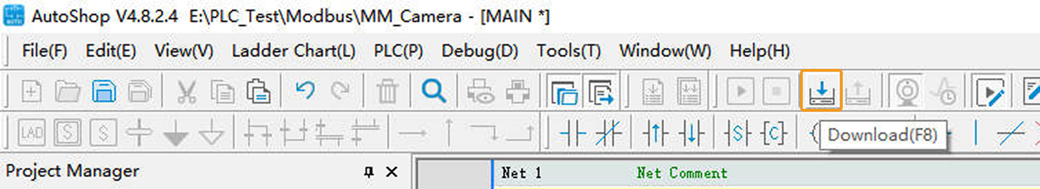
In the toolbar, click the Download icon.
-
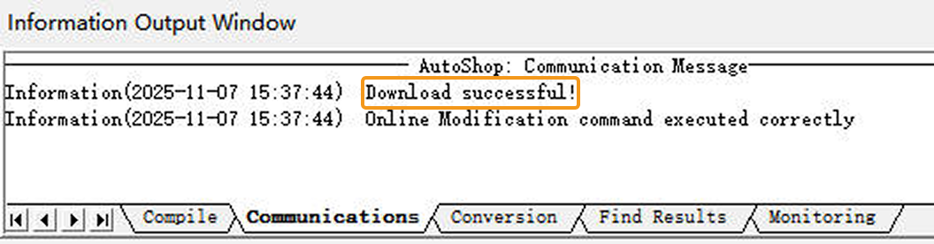
In Information Output Window, click the Communications tab. If the download is successful, a message Download successful will be displayed here.
Run the Mech-Vision Project
-
In the AutoShop software toolbar, click the Write icon.
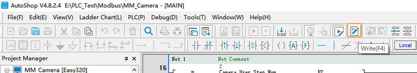
-
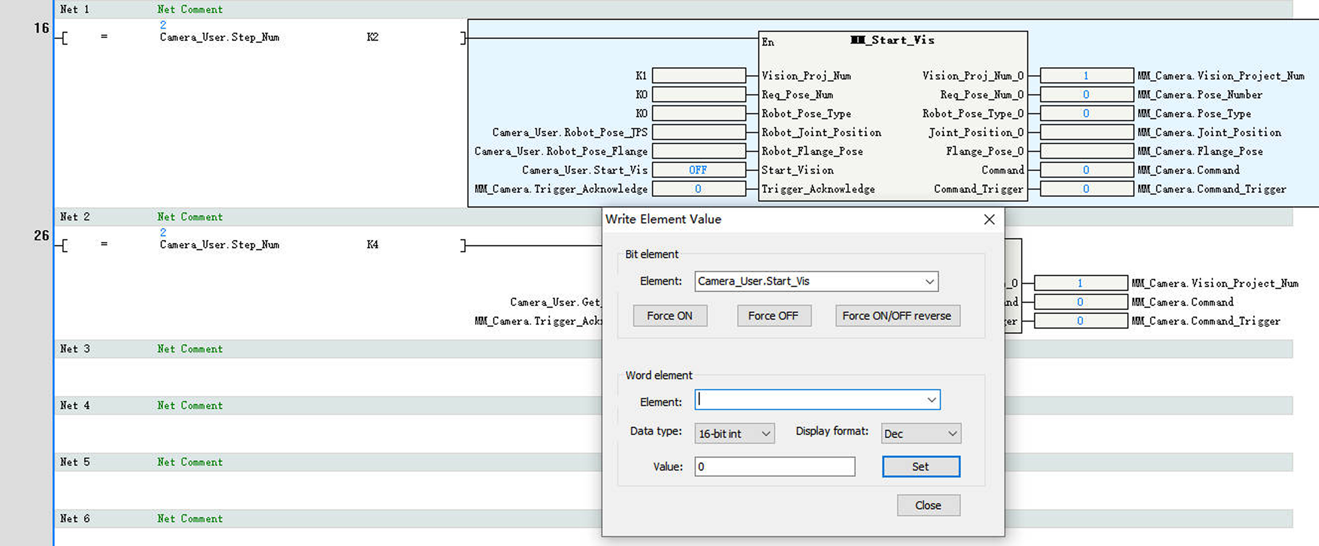
In the Write Element Value dialog box, perform the following operations:
-
Under Word Element, select Camera_User.Step_Num for Element, set Value to 2, and click Set to enable the MM_Start_Vis function.
-
Under Bit Element, select Camera_User.Start_Vis for Element, click Force ON to trigger the Mech-Vision project. Then, click Force OFF to reset Camera_User.Start_Vis.
-
-
In Information Output Window, click the Monitoring tab. If the Status_Code value is 1102, it indicates that the Mech-Vision project has been successfully triggered to run.
If 10XX is displayed for Status_Code, refer to Status Codes and Troubleshooting for troubleshooting. 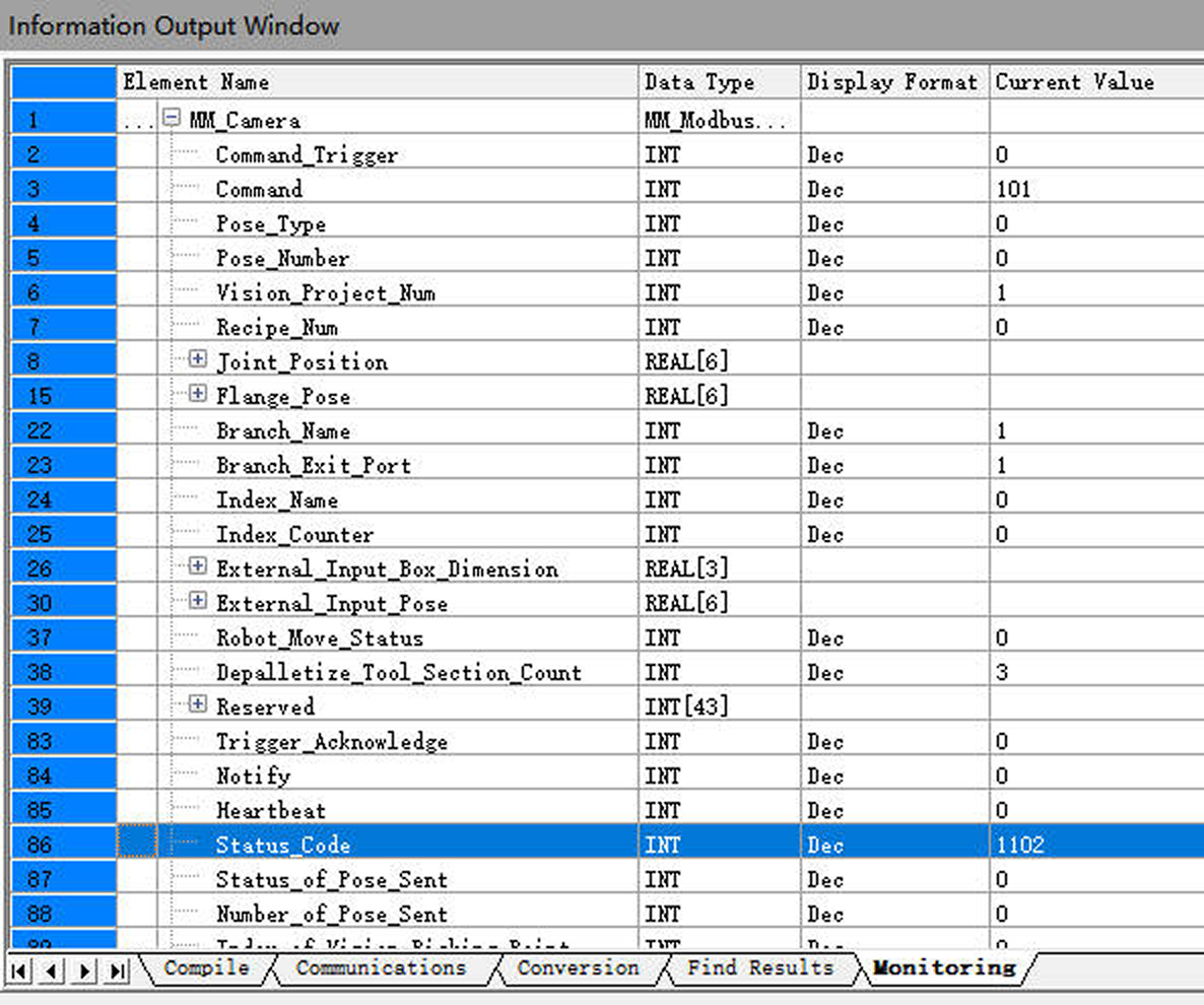
Get Vision Result from Mech-Vision
-
In the Write Element Value dialog box, perform the following operations:
-
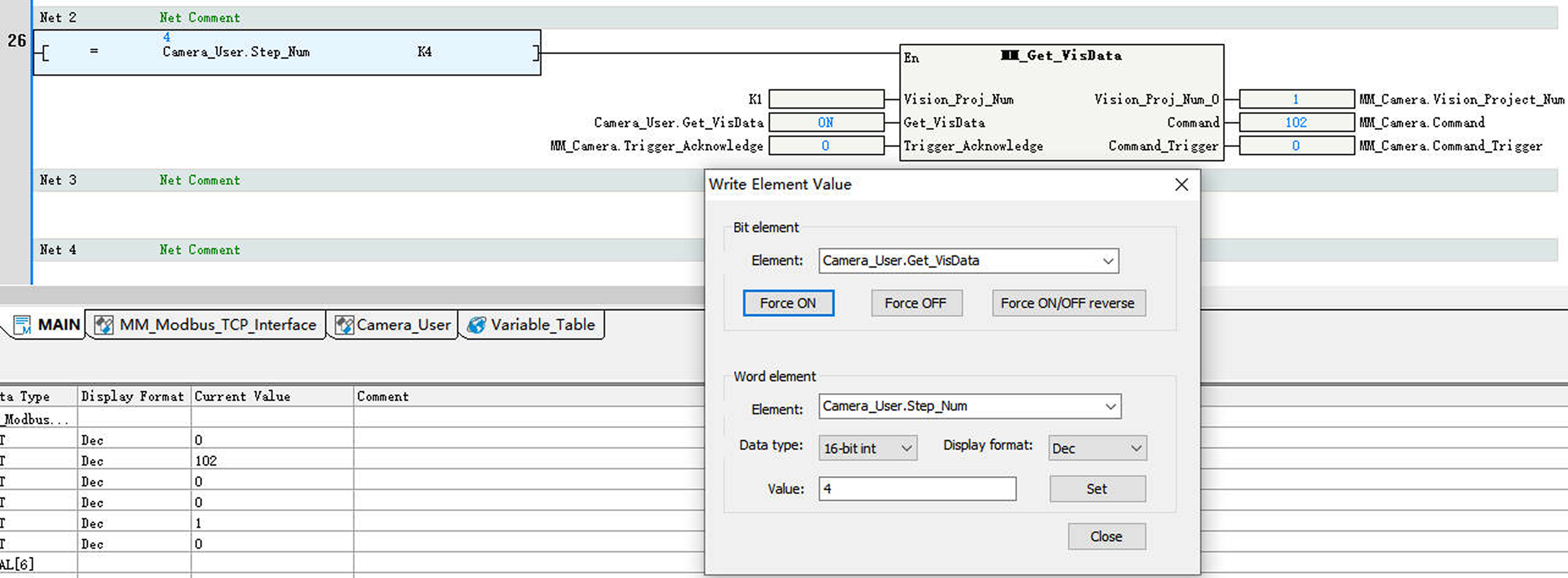
Under Word Element, select Camera_User.Step_Num for Element, set Value to 4, and click Set to enable the MM_Get_VisData function.
-
Under Bit Element, select Camera_User.Get_VisData for Element, click Force ON to obtain the vision result. Then, click Force OFF to reset CameraUser.Get_VisData.
-
-
In Information Output Window, click the Monitoring tab. If the Status_Code value is 1100, it indicates that the vision result has been successfully obtained. Check the values of Target_Pose. The values indicate the pose data of vision points.
If 10XX is displayed for Status_Code, refer to Status Codes and Troubleshooting for troubleshooting. 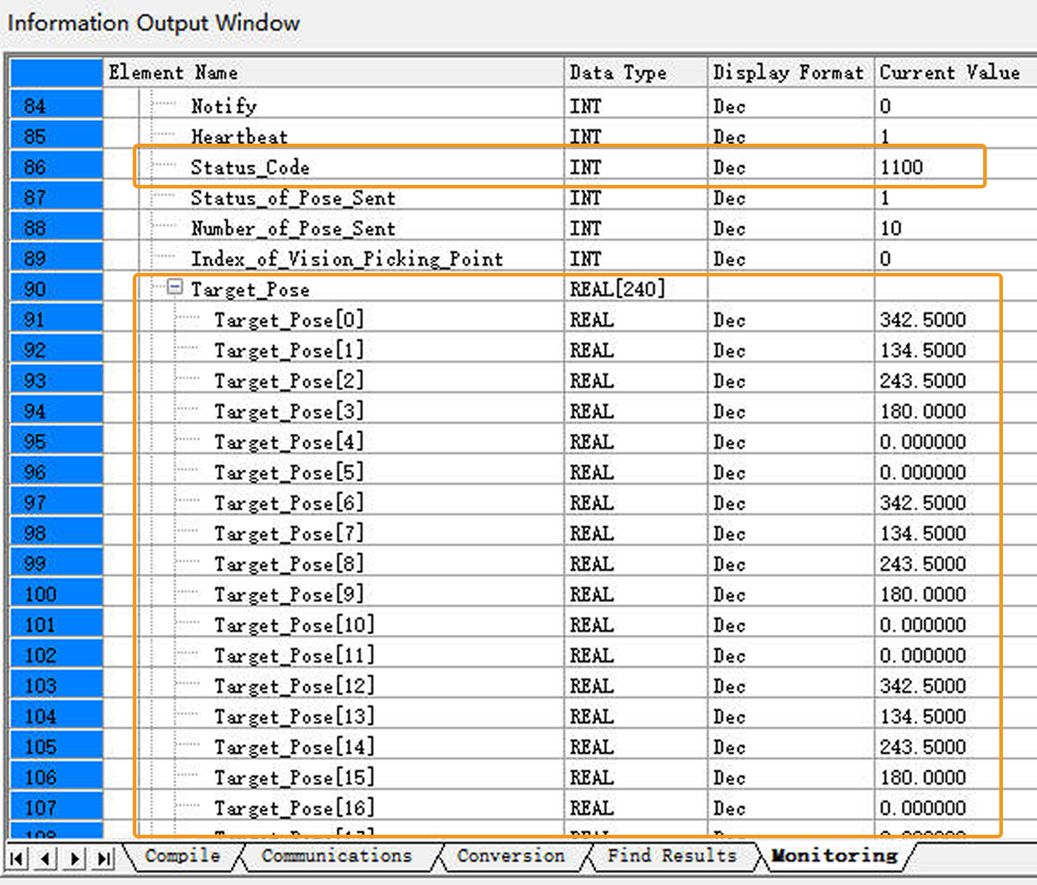
Obtain Planned Path from Mech-Viz
Parameter Settings
-
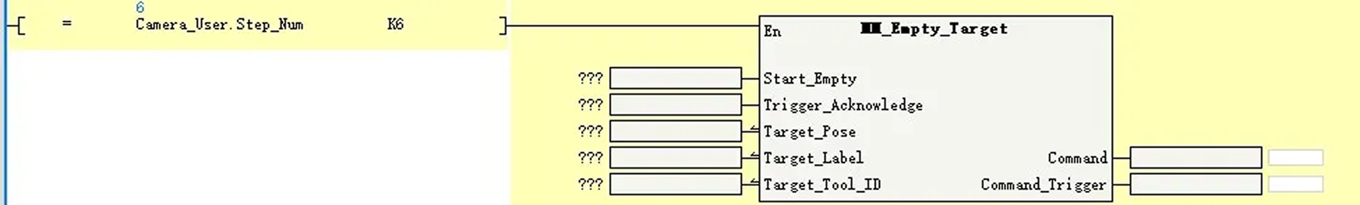
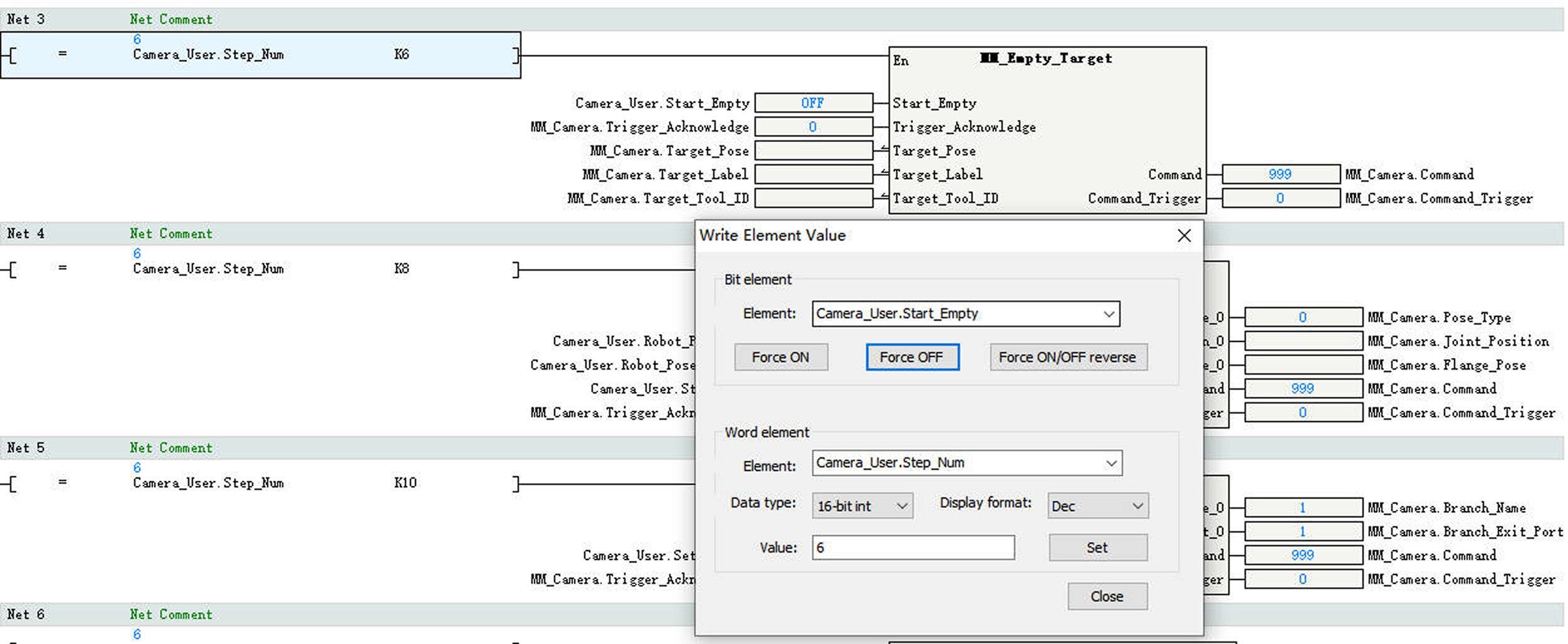
In the Project Manager panel, double-click MAIN. In Net 3, enter the comparison command LD= Camera_User.Step_Num K6. Then apply the command MM_Empty_Target.
-
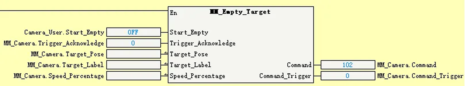
Add the corresponding variables to the input and output ports of MM_Empty_Target as shown in the figure below.
-
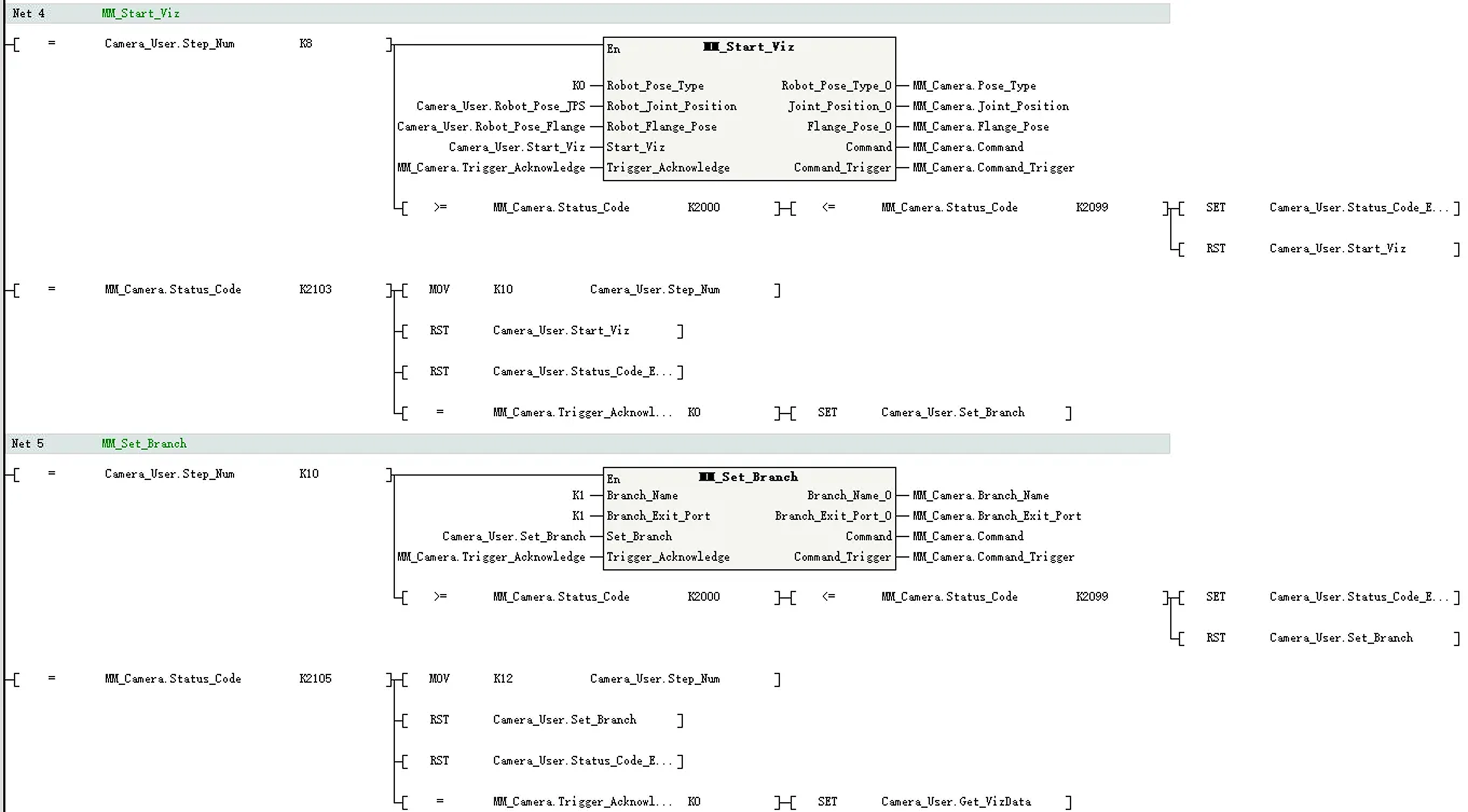
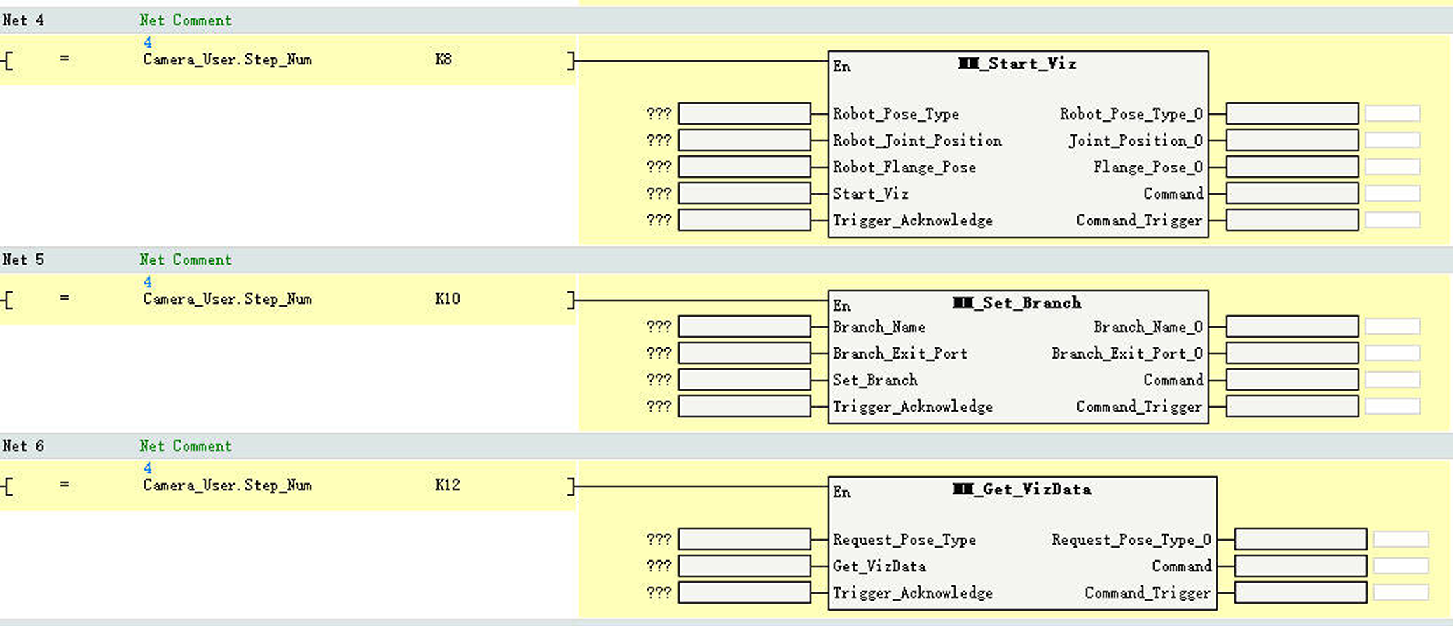
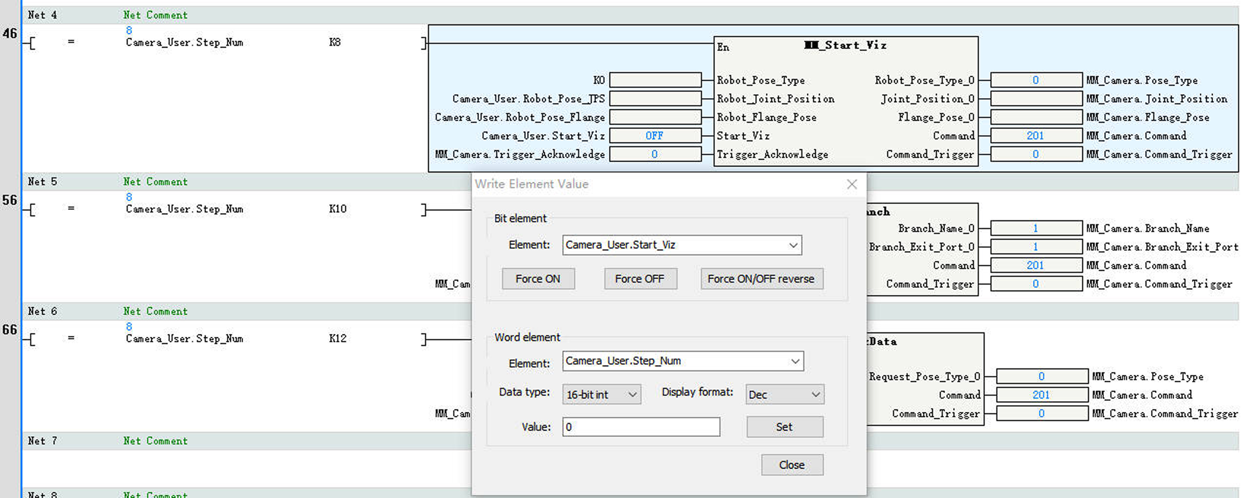
In Net 4, enter the comparison command LD= Camera_User.Step_Num K8. Then apply the command MM_Start_Viz.
-
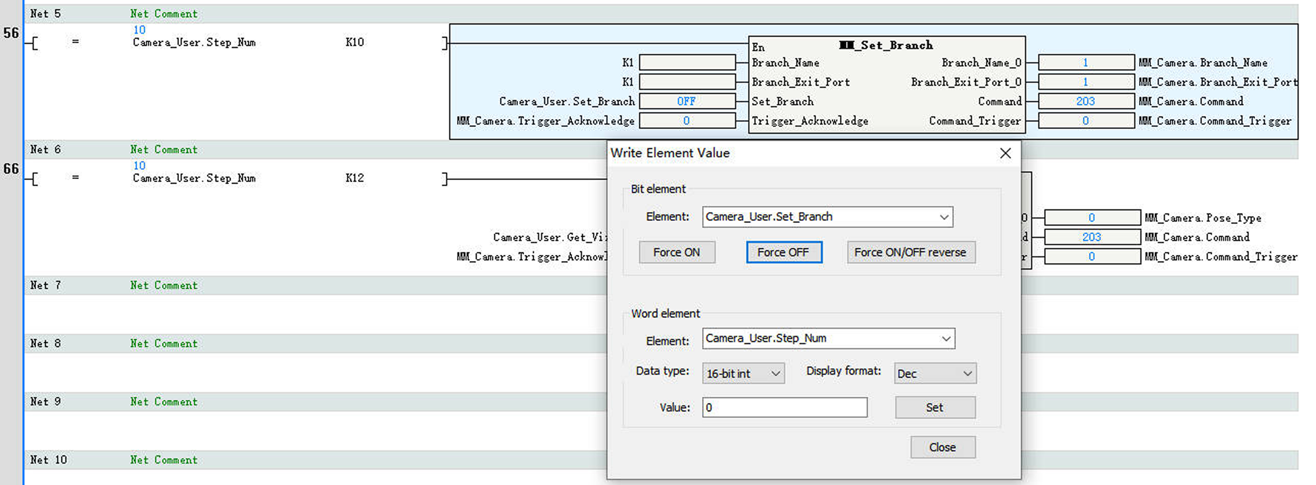
In Net 5, enter the comparison command LD= Camera_User.Step_Num K10. Then apply the command MM_Set_Branch.
-
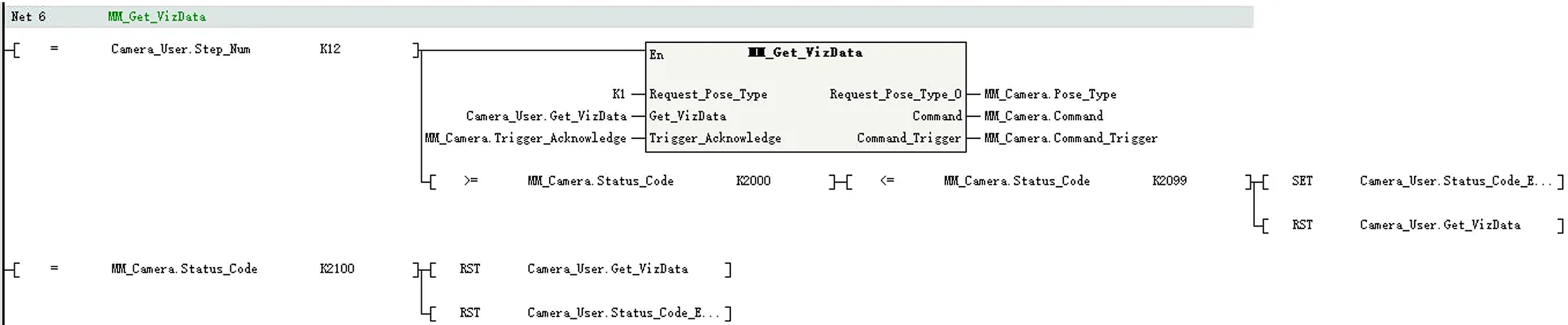
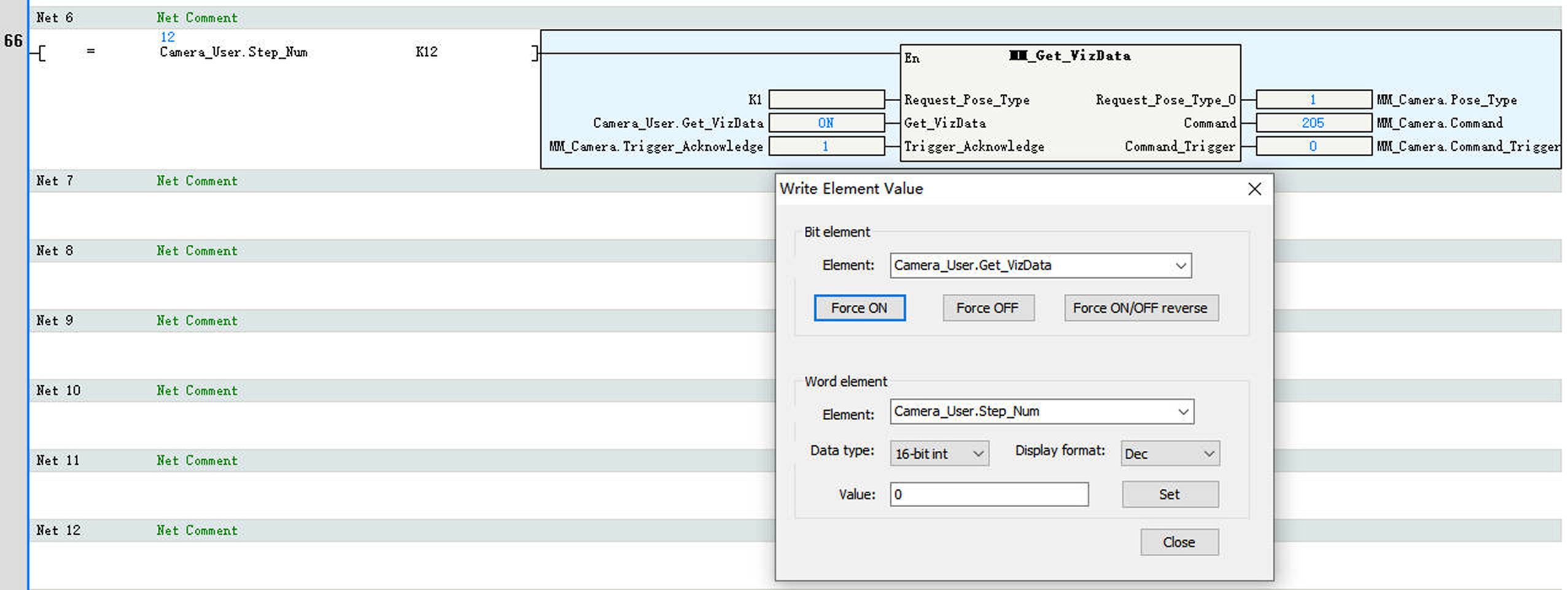
In Net 6, enter the comparison command LD= Camera_User.Step_Num K12. Then apply the command MM_Get_VizData.
-
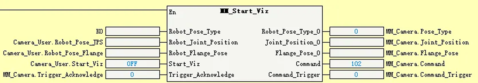
Set the input and output ports of MM_Start_Viz as shown in the figure below.
-
Set the value of Robot_Pose_Type to 0. Then, the image-capturing pose does not need to be sent to the Mech-Viz project. For example, the image-capturing pose does not need to be sent when the camera is mounted in eye-to-hand mode.
-
Add the corresponding variables to the remaining ports as shown in the figure below.
-
-
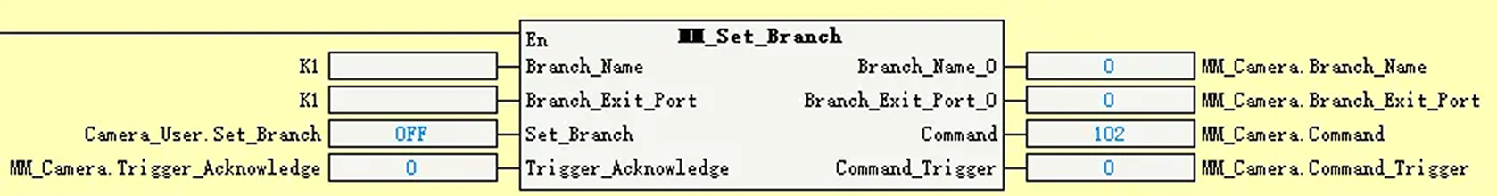
Set the input and output ports of MM_Set_Branch as shown in the figure below.
-
Set the values of Branch_Name and Branch_Exit_Port both to 1 to indicate that the project takes port No.1 of the Branch by Msg No.1 Step of the Mech-Viz project.
-
Add the corresponding variables to the remaining ports as shown in the figure below.
-
-
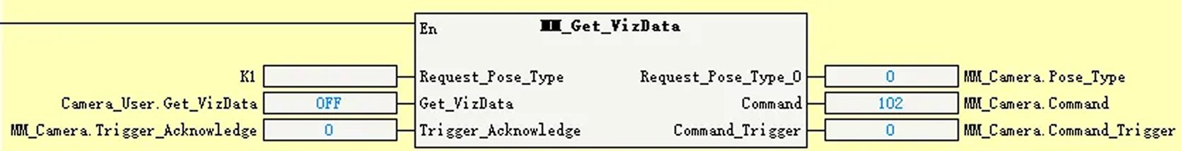
Set the input and output ports of MM_Get_VizData as shown in the figure below.
-
Set the value of Request_Pose_Type to 1 to indicate that the waypoints planned by Mech-Viz will be returned in joint positions.
-
Add the corresponding variables to the remaining ports as shown in the figure below.
-
-
In the toolbar, click the Download icon.
-
In Information Output Window, click the Communications tab. If the download is successful, a message Download successful will be displayed here.
Run the Mech-Viz Project
-
In the AutoShop software toolbar, click the Write icon.
-
In the Write Element Value dialog box, perform the following operations:
-
Under Word Element, select Camera_User.Step_Num for Element, set Value to 6, and click Set to enable the MM_Empty_Target function.
-
Under Bit Element, select Camera_User.Start_Empty for Element, click Force ON to clear the obtained vision result. Then, click Force OFF to reset CameraUser.Start_Empty.
-
-
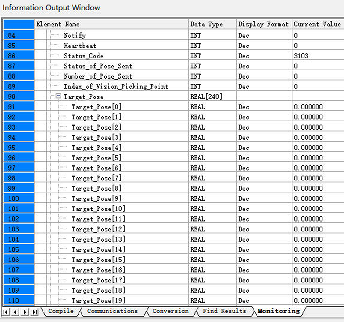
In Information Output Window, click the Monitoring tab. If the Status_Code value is 3103, it indicates that the variable values Camera_User.Target_Pose, Camera_User.Target_Label, and Camera_User.Target_Tool_ID have been successfully cleared.
-
In the Write Element Value dialog box, perform the following operations:
-
Under Word Element, select Camera_User.Step_Num for Element, set Value to 8, and click Set to enable the MM_Start_Viz function.
-
Under Bit Element, select Camera_User.Start_Viz for Element, click Force ON to trigger the Mech-Viz project. Then, click Force OFF to reset Camera_User.Start_Viz.
-
-
In Information Output Window, click the Monitoring tab. If the Status_Code value is 2103, it indicates that the Mech-Viz project has been successfully triggered to run.
If 20XX is displayed for Status_Code and you want to troubleshoot the issue, see Status Codes and Troubleshooting. 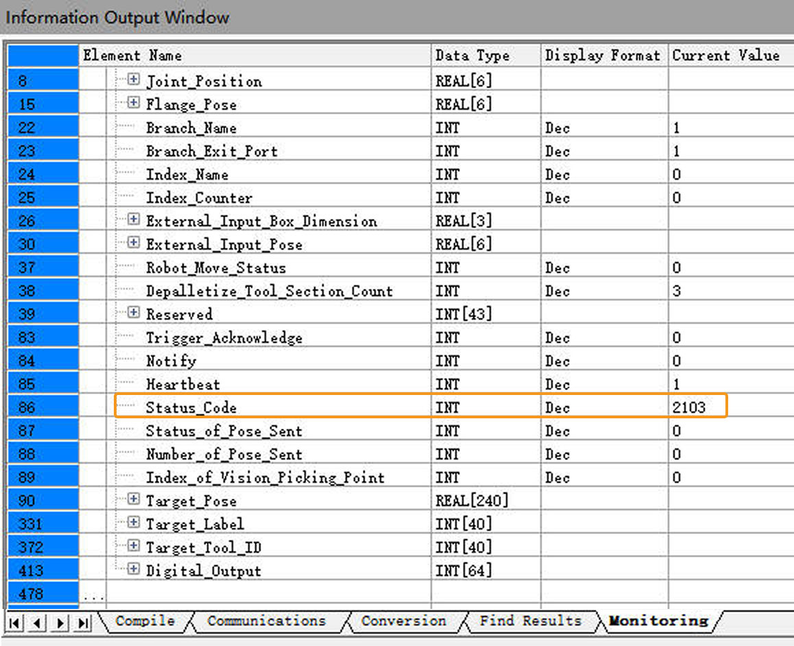
Set the Exit Port for the Branch by Msg Step in Mech-Viz
-
In the Write Element Value dialog box, perform the following operations:
-
Under Word Element, select Camera_User.Step_Num for Element, set Value to 10, and click Set to enable the MM_Set_Branch function.
-
Under Bit Element, select Camera_User.Set_Branch for Element, click Force ON to set the exit port of the Branch by Msg Step in Mech-Viz. Then, click Force OFF to reset CameraUser.Set_Branch.
-
-
In Information Output Window, click the Monitoring tab. If the Status_Code value is 2105, it indicates that the exit port has been successfully set for the Branch by Msg Step in Mech-Viz.
If 20XX is displayed for Status_Code and you want to troubleshoot the issue, see Status Codes and Troubleshooting. 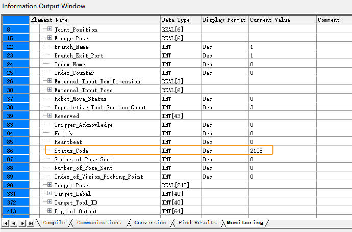
Get Planned Path in Mech-Viz
-
In the Write Element Value dialog box, perform the following operations:
-
Under Word Element, select Camera_User.Step_Num for Element, set Value to 12, and click Set to enable the MM_Get_VizData function.
-
Under Bit Element, select Camera_User.Get_VizData for Element, click Force ON to obtain the planned path from Mech-Viz. Then, click Force OFF to reset CameraUser.Get_VizData.
-
-
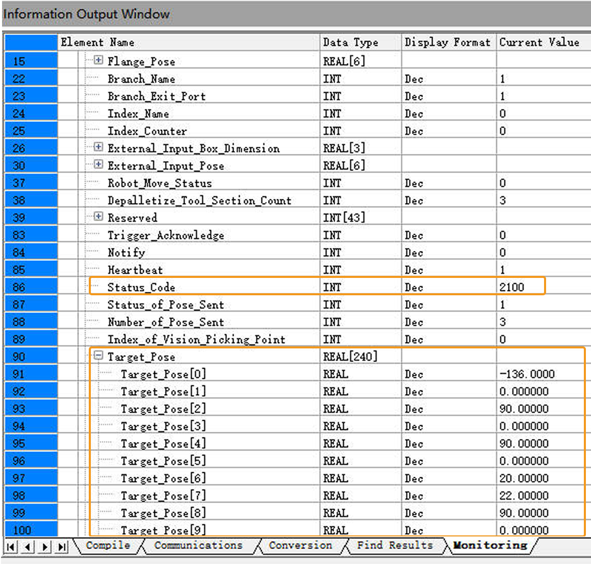
In Information Output Window, click the Monitoring tab. If the Status_Code value is 2100, it indicates that the planned path has been successfully obtained. Check the values of Target_Pose. The values indicate the pose data of waypoints.
If 20XX is displayed for Status_Code and you want to troubleshoot the issue, see Status Codes and Troubleshooting.