Structural Design of Vacuum Grippers
This section takes vacuum grippers as an example to introduce the structural design of vacuum grippers in the logistics industry, including standard component selection, vacuum system design, and other accessory design.
Main Structure Design
When designing the main structure of the vacuum gripper, pay attention to the following points.
-
Ensure the main structure is strong and rigid
The main structure of the vacuum gripper must be robust. Perform stress simulations if necessary. For some load-bearing parts, aluminum profiles with poor rigidity are not recommended.
-
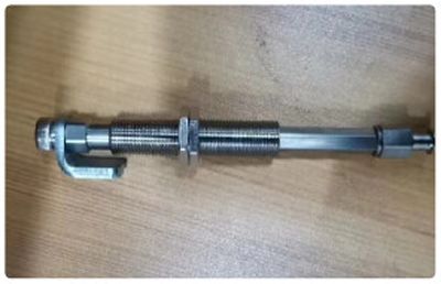
Add a buffering device
Adding buffers in the vertical direction of the vacuum gripper can protect both the target object and the gripper. When designing a larger vacuum gripper, it is also necessary to consider that unilateral force may cause the gripper to fail to return to its original shape after being depressed.
-
Consider rotational effects
When a specific picking or placing pose is required, it is usually undesirable for the target object to rotate while being held by the vacuum gripper. Therefore, the selected vacuum gripper adapter should include an anti-rotation feature. If the suction surface of the target object has an unknown tilt angle, an adapter should be added to the end of the vacuum gripper to accommodate this tilt angle.
Suction Cup Selection
When selecting suction cups, pay attention to the following points.
-
Suction cup service life
Bellows suction cups, also known as accordion suction cups, generally have a longer service life than foam suction cups.
-
Suction cup inertia
In general, the heavier the object picked by the suction cup, the greater the inertia, which can negatively affect the robot’s motion performance when carrying the vacuum gripper.
-
Suction cup material
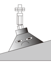
Soft suction cups conform more easily to the surface of cartons, so soft-material suction cups (e.g., silicone bellows suction cups) are generally preferred.
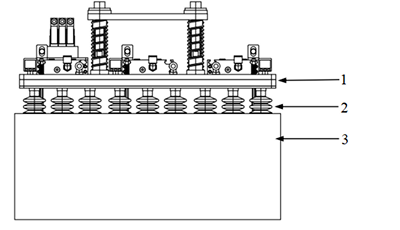
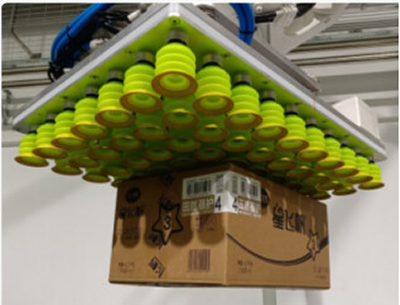
However, if the carton is heavy, the soft suction cup may not be able to pick the carton securely. In this case, a hard suction cup should be selected.
The figures below show such a case. 1 is the vacuum gripper body, 2 is the suction cup nozzle, and 3 is the carton.
Vacuum System Selection
When designing the vacuum system, pay attention to the following points.
-
Consider vacuum system airflow
When a large airflow is required, a fan is usually selected. To ensure balanced flow through the check valve inside the gripper and improve overall performance, it is recommended to install a relief valve on the fan.
-
Consider gas leakage
When there is a large leakage of compressed gas, the suction force decreases significantly. In this case, improve the performance of the vacuum source and appropriately increase the effective cross-sectional area of the air supply lines to enhance suction capability.
-
Consider factors affecting suction force
The distance between the vacuum generator and the suction cup, as well as the size of the connecting tubing, can affect the actual suction force of the suction cup. It is generally recommended to keep the distance between the vacuum generator and the vacuum gripper as short as possible and select tubing with an appropriate diameter to reduce flow resistance.
-
Consider extreme situations
In the event of power loss or other extreme conditions, normally closed supply valves or valves with a hold function should be selected. When a vacuum breaker valve is present, a throttle valve should be used to adjust the vacuum-break flow to improve the controllability and stability of the vacuum release process.
Sensor Design
When designing sensors, pay attention to the following points.
-
Properly set the position and number of drop-detection sensors
To accommodate various carton sizes and picking methods, set the positions and number of drop-detection sensors (photoelectric sensor + probe) according to actual needs.
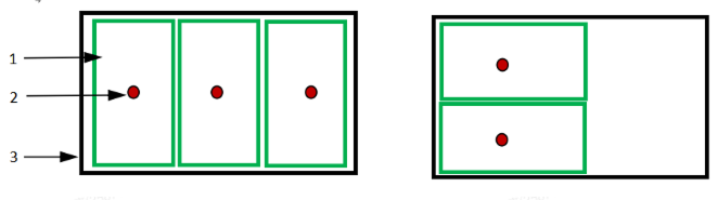
The figure below shows common carton picking methods, where 1 is the carton, 2 is the sensor position, and 3 is the suction cup.
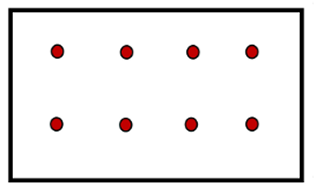
The arrangement of sensor positions and numbers should take into account both picking methods shown above, as illustrated in the figure below.
-
Consider extreme situations
When arranging sensors, comprehensively consider the suction paths of the vacuum gripper and the coverage range of the smallest cartons. For example, in some cases, sensors may detect the edge of a carton; if the robot moves slightly during operation, this may cause false detections. To reduce this risk, the distance between the two sensors can be slightly decreased to improve detection stability.
-
Watch sensor service life
For sensor components with relative motion, pay attention to their service life. Optimization can be achieved through structural design and material selection; for example, moving parts in the probe can use stainless steel to improve wear resistance and reliability. In addition, the sensor mounting sheet metal is recommended to be at least 3 mm thick to ensure mounting strength and stability.
Barcode Reader Design
When designing the barcode reader, pay attention to the following points.
-
Consider barcode placement
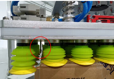
Since the vacuum gripper slightly compresses during picking, it is usually required to maintain a certain distance between the barcode and the top of the carton when reading the code after the robot picks up the carton. The recommended distance is 70 mm to 150 mm. Otherwise, the barcode reading success rate may be affected for the picking pose shown in the figure below.
-
Consider barcode print quality
In the logistics industry, 1D barcodes are commonly used, typically with a precision of 0.2 mm – 0.5 mm. To ensure reliable barcode reading, the print quality is generally required to meet at least grade B.
-
Prefer dynamic reading
In fast-paced carton picking scenarios, dynamic barcode reading should be used whenever possible instead of static reading.
-
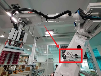
Determine the barcode reader mounting configuration
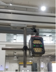
Common barcode reader mounting configurations are shown in the figure below.
-
Stationary mounting: Commonly used next to production lines or in scenarios where robots cooperate to scan logistics products.
-
Mounted on the robot end-effector: Allows multi-degree-of-freedom and multi-pose scanning. When the target object surface is covered with transparent material, or barcodes must be read through materials such as acrylic, avoid light sources near the barcode that may create glare and affect reading accuracy.
-
Mounted on the upper arm of the robot: This mounting method integrates code reading with robot motion, helping to improve production efficiency.
-
-
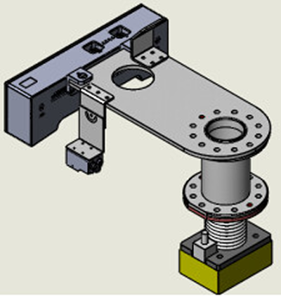
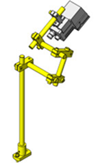
Consider barcode reader frame design
The barcode reader frame should allow for adjustment in multiple directions. In practice, it can be simplified based on the frame shown in the figure below.
Other Accessory Design
When designing other accessories, pay attention to the following points.
-
Air hose free length
The free length of the air hose should be designed according to the six-axis motions of the robot to avoid bending.
-
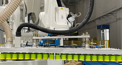
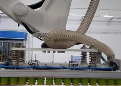
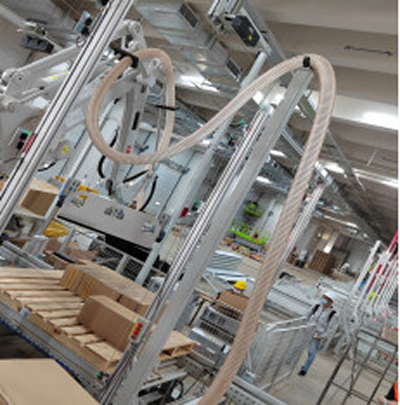
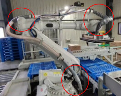
Air hose routing
The overall routing of the air hose should be as smooth and flexible as possible. Since the robot may operate at different stations, the air hose can be elevated (as shown in the figure below), while also considering the airflow and pressure provided by the fan.
-
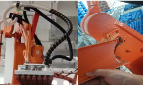
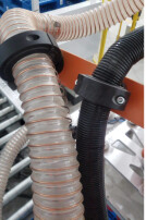
Air hose abrasion protection
In areas where the air hose comes into direct contact with the robot, vacuum gripper, or other components, wear-resistant cloth or protective tubing should be used to extend the service life of the hose.
-
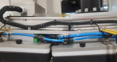
Pipeline layout
The layout of the air hose and other pipelines should be considered comprehensively to prevent collisions and friction during robot motion, which could cause gas leaks.
-
Component service life
For scenarios with high loads or intermittent impacts, the service life of accessories should be carefully considered to prevent component breakage during robot motion.