Camera Protection Device Design
When using cameras in extreme environments, some factors including high temperature, low temperature, and welding spatter can cause damage to the camera, affecting the camera’s imaging performance and lifespan. To address these issues, protective device can be mounted for the camera. This article will introduce how to design camera protection devices for welding, high-temperature, and low-temperature scenarios respectively.
Welding & High-Concentration Dust Scenarios
Case Analysis
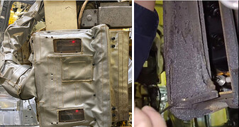
In welding and high-concentration dust scenarios, prolonged exposure of the camera leads to the accumulation of a large amount of welding spatter, dust, and splatter on both the camera body and lens, ultimately affecting the imaging and point cloud quality of the camera.
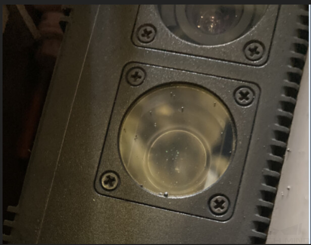
The figure below shows the comparison of the point cloud acquired before and after the attachment of the welding spatter on the on-site camera in a project. It can be seen from the figure that the quality of the point cloud in the right image has significantly decreased.

Solution Design
Solution 1: Paste the Tempered Glass Lens Protector
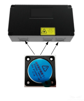
In the welding and high-concentration dust scenarios, the common method to protect the camera is to paste the tempered glass lens protector on the camera lens.
-
Technical Specifications of the Tempered Glass Lens Protector:
Technical specifications Value Refractive index
1.51
Transition temperature
820 ℃
Flexural strength
1.542
Expansion coefficient
0.035%–0.055%
-
Impact of the Tempered Glass Lens Protector Thickness on the Camera:
When selecting tempered glass lens protector, it is necessary to consider the impact of the thickness on the camera. The tempered glass lens protectors with different thicknesses have varying effects on the camera, as outlined in the table below. Based on multiple tests, it is recommended to use the tempered glass lens protector in the thickness from 0.22 mm to 0.33 mm.
Thicker Thinner -
During welding operations, welding spatter tends to accumulate at the edges of the tempered glass lens protector.
-
When pasting the tempered glass lens protector, it is highly prone to causing bubbles between the protector and the camera lens, which cannot be manually squeezed out, ultimately resulting in water mark.
The protective effect is relatively poor, but the quality of the point cloud is high.
-
-
Precautions:
During the actual production, the tempered glass lens protector should be replaced regularly according to the cycle time. It is not recommended to replace the entire lens to solve the problem of welding spatter or dust accumulation in front of the lens (as shown in the figure below). The reasons are as follows:
-
Frequent disassembly of the lens may cause loosening or detachment of the bolts that fix the lens.
-
Compared to the camera assembly environment, the on-site environment is complex. Repeatedly disassembling the camera on site may expose the camera’s interior to dust contamination, which could affect the camera’s lifespan and the point cloud quality.
-
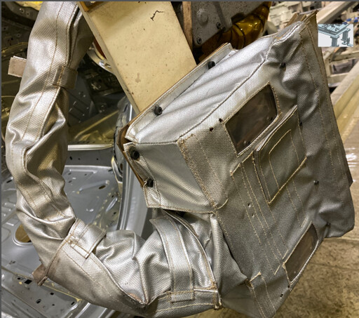
Solution 2: Use Semi-enclosed Camera Protection Case
The semi-enclosed camera protection case utilizes hinges to connect the outer housing and the cover plate of the protection case. Open the protection case when capturing, and close it after capturing is completed. This ensures that the camera is not affected by dust, welding spatter, and other debris in welding operation and dust environment.
-
Principles of Design:
When designing a semi-enclosed camera protection case, you should pay attention to the following points.
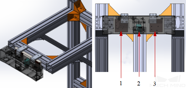
Precaution Description Illustration Easy disassembly, installation, and maintenance
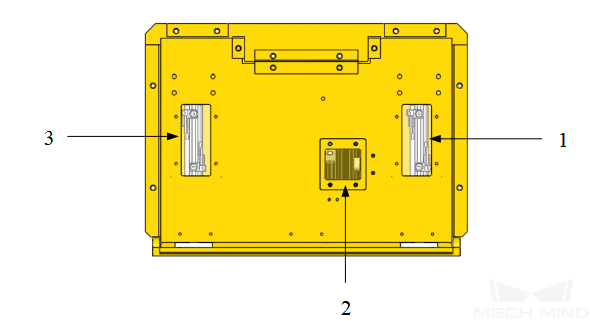
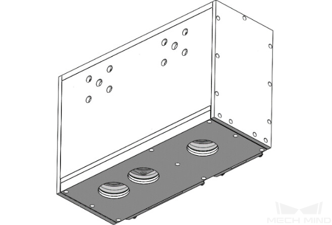
Ensure easy observation of the camera indicator light, and facilitate operation of regulator valves and switches. As shown in the right figure, 1 and 3 are the openings for adjusting magnetic switches, while 2 is the opening for adjusting the speed control valve.
Sealing
Special attention should be paid to sealing the hinge, and the openings where the cables and air pipes pass through to enhance the protective and sealing performance of the protection case.
Wrapping the protection cover
In some particularly harsh environments, it is advisable to wrap the protection cover around the camera protection case. The material for the protection cover can be chosen based on the ambient temperature or customer requirements.
Regular maintenance
After using the camera protection case for a period of time, regular maintenance should be applied to remove the welding spatter and dust. If the protection case is corroded, it needs to be replaced.
-
Key Points for Mounting Cables:
-
For cameras in the EIH setup, the camera cables and protection case cables should be comprehensively considered based on the actual situation to achieve unified design and layout.
-
The camera, cylinder air pipes, and cables can be protected with customized fire-retardant dresspacks. It is recommended to use a dresspack with a side-opening design for easy installation and maintenance.
-
If a spring balancer is required, please ensure that the camera cable dresspack is evenly stressed to reduce collisions and friction with other cables, while also facilitating installation and maintenance.
-
For easy disassembly and maintenance, it can be considered to use M12 connectors to facilitate quick replacement and maintenance of cylinder signal lines.
-
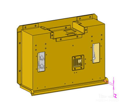
Solution 3: Use Enclosed Camera Protection Case
In harsh environments, fully enclosed camera protection case can be considered. The protection case is made of sheet metal and can create a sealed space, providing an enclosed and independent environment for the camera.
-
Principles of Design:
-
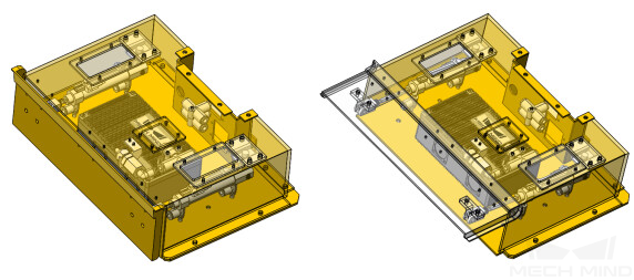
To enhance the lifespan of camera protection case, it can be considered to use the removable tray design at the bottom for easy replacement. As shown in the following figure, 1 and 2 are the structure of removable tray, while 3 is the fastener.
-
To reduce the impact of camera protection case on the camera imaging, please pay attention to the following points in terms of the design and installment of glass observation window.
-
Place the glass window as close to the camera window as possible.
-
The surface of the glass window should be as parallel to the camera window as possible.
-
Please avoid deformation caused by external forces when the glass window is assembled and used.
-
-
The flat glass with high flatness should be selected as the glass window, and the glass chosen should also meet the requirements as shown in the table below. Through multiple tests, it is recommended to use K9 and H-K9L (environmentally friendly K9) glass manufactured by CDGM, as well as BK7 and N-BK7 (environmentally friendly BK7) glass manufactured by Schott in Germany.
Technical specifications Value Thickness
1–3 mm (As thin as possible with high flatness)
Refractive index
1.52
Abbe number
64.2
Coating
Double-sided AR coating (visible light transmission greater than 98.5%)
-
High Temperature Environment
In high-temperature environments, when designing camera protection devices, attention should be paid to increasing the airflow velocity around the outer surface of the camera or implementing vortex tube cooling. The following text will introduce the two design principles mentioned above separately.
Increase the Airflow Velocity around the Outer Surface of the Camera
This design is suitable for scenarios where the temperature is relatively low (around 40°C of radiant heat around the camera) and there is good ventilation around the camera. In actual projects, it is common to use air knives or valve stems, as well as exhaust fans with temperature control switches, to increase the airflow velocity around the outer surface of the camera.
-
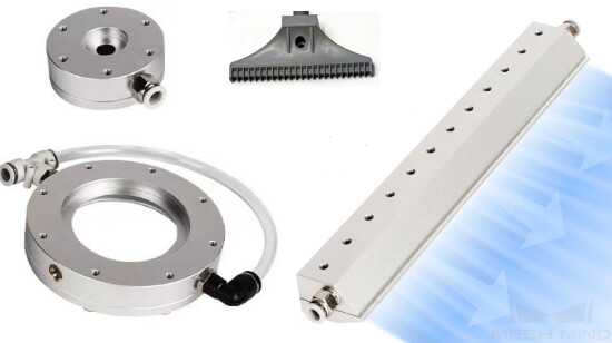
Air Knives or Valve Stems
Air knives or valve stems can blow compressed air directly onto the surface of the camera to cool it. The commonly used air knives and valve stems are shown in the following figure.
The advantages and disadvantages of using air knives or valve stems to increase the airflow velocity around the outer surface of the camera are shown in the table below.
Advantages
Disadvantages
The cost is low, and it is easy to cool the surface of the camera by increase the airflow velocity.
-
The on-site compressed air supply should meet certain requirements, such as being free of water and oil, and the dust filtration precision should be around 40 microns.
-
High air consumption leads to high maintenance costs.
-
There is a high level of noise during operation.
-
-
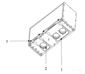
Exhaust Fans with Temperature Control Switches
The temperature control switch can sense the temperature of the camera’s external surface. When the temperature exceeds the set threshold, it triggers the operation of the fan to increase air convection on the surface of the camera, achieving heat dissipation and cooling effect. The specific structure is shown in the figure below, where 1 and 3 are the exhaust fans, and 2 is the temperature control switch.
The advantages and disadvantages of using exhaust fans with temperature control switches to increase the airflow velocity around the outer surface of the camera are shown in the table below.
Advantages
Disadvantages
-
It can reduce the usage and maintenance costs.
-
There is no need to provide compressed air.
-
The cooling performance is affected by the ambient environment.
-
The cost is relatively high.
-
Implement Vortex Tube Cooling
This design is suitable for scenarios with high temperatures and enclosed environments, especially when the camera is subjected to intense heat radiation, and the passive heat dissipation function of the camera cannot meet the cooling requirements, resulting in the camera temperature exceeding 45°C.
-
Mechanism:
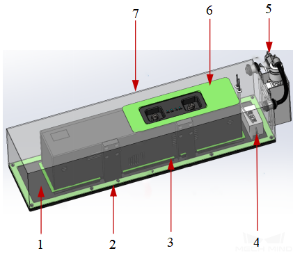
The vortex tube generates cold air, which is directed towards the surface of the camera. The temperature controller inside the device controls the on/off operation of the vortex tube, maintaining the temperature approximately at the set value.
The camera protection case is shown in the figure below, where 1 is the mounting plate, 2, 3, 6 are rubber gaskets, 4 is the temperature controller, 5 is the vortex tube, and 7 is the upper housing.
-
Principles of Design:
-
In scenarios with intense heat radiation, it is recommended to design a double-layer insulation case with insulation material filled in the middle, such as glass fiber, asbestos, mineral wool, silicate, aerogel felt, and vacuum insulation panel, to enhance the insulation effect.
-
To address the issue of condensation on the surface of the protection case and the camera enclosure, fans can be added inside the protection case to improve surface temperature differentials and prevent moisture condensation.
-
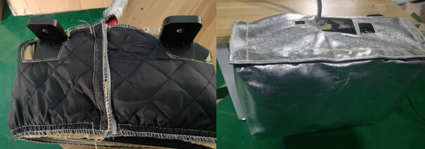
Low Temperature Environment
In low temperature environments, it is common to use thermostatic protection cover to provide thermal insulation for the camera.
-
Mechanism:
The basic principle of the thermostatic protection cover is to monitor the internal temperature in real time using a temperature sensor. When the temperature drops too low, an electric heating plate is used to raise the temperature to maintain a constant temperature. Please note that during seasonal changes, the camera protection cover may lead to poor heat dissipation of the camera.
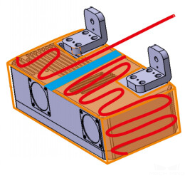
In general, the thermostatic protection cover consists of an insulation layer and a heating layer, as shown in the figure below.
-
Principles of Design:
-
Ensure that the camera brackets and lenses come out through the corresponding holes.
-
Ensure that the thermistor is smooth and free from distortion.
-
It is recommended to install the temperature sensor at the mainboard.
-