Gripper Design
This section introduces the principles of design and examples of the gripper in the neatly arranged cylindrical shaft loading application.
Principles of Design
-
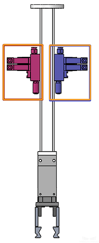
If the grippers are symmetrical or highly similar (as shown in the figure below, the left and right sides of the same valve are symmetrical), be sure to set up an error-proofing mechanism to avoid inconsistencies between the on-site installation and the drawings, which may lead to the failure of the path planning in Mech-Viz.
-
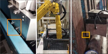
The positioning mechanism and suction mechanism at the end of the magnetic gripper should be properly coordinated to avoid the picking deviation as shown in the figure below.
-
The magnetic force of the electromagnet should not be excessively strong. When using an electric permanent magnet, select a suction force with a safety factor of 3–5 based on the workpiece surface conditions. If using a standard rechargeable electromagnet, the suction force should generally be 5–10 times the weight of the workpiece.
-
The gripper structure should be compact. During the initial design phase, careful consideration should be given to potential interference issues that may arise from the gripper body, bolts, and pipelines during picking.
-
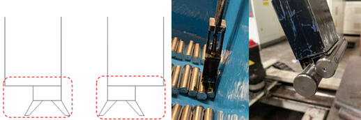
When designing the magnetic gripper’s end, avoid situations depicted in the left figure below. Otherwise, when the gripper is picking in the corner of the bin, there is a significant risk of simultaneously picking two workpieces.
Design Examples
This section will introduce the design cases of grippers used in some scenarios, and the details are as follows.
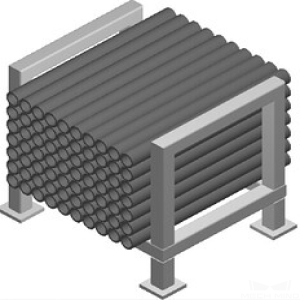
Compactly Arranged Workpieces
| Picking method | Applicable scenarios | Infeed workpieces | Gripper example | Figure legends |
|---|---|---|---|---|
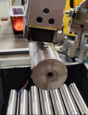
Picking by magnetic force |
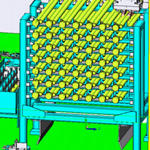
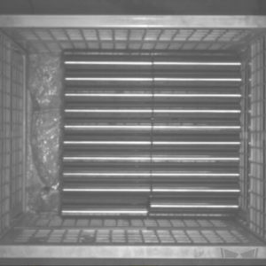
Workpieces are placed in an orderly manner and there is no interference in picking the circular surface. |
|
|
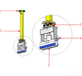
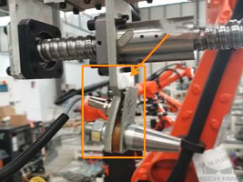
1. Mounting flange
|
Picking by workpiece ends |
There is enough picking space at both ends of the workpiece, and the ends can be securely picked. |
|
|
1. Left gripping plate
|

|
Workpieces Arranged with Gaps in Between
| Applicable scenarios | Infeed workpieces | Gripper example | Figure legends |
|---|---|---|---|
The incoming workpieces are placed with gaps, and there are gaps between workpieces on the same layer and between workpieces on the upper and lower layers. |
|
|
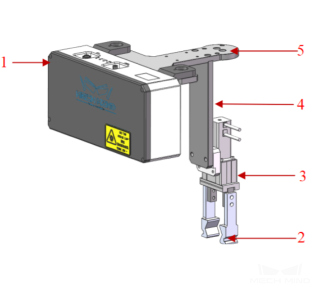
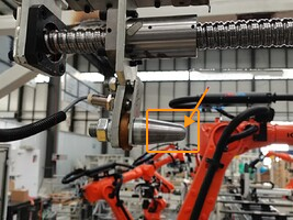
1. Camera
|