Troubleshooting
This section shows the common problems that might occur in the implementation of the single-case sack depalletizing solution and the corresponding causes and solutions.
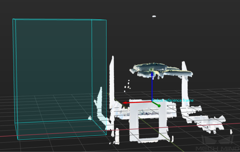
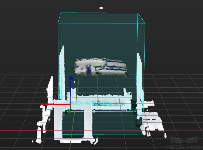
Problem 1: No Workpiece in 3D ROI
Symptoms
The Point Cloud Preprocessing Procedure encountered a failure during execution, and the log panel of Mech-Vision displayed an error message of “Watched step ‘Extract 3D Points in 3D ROI_1’ has no output: no workpiece.”
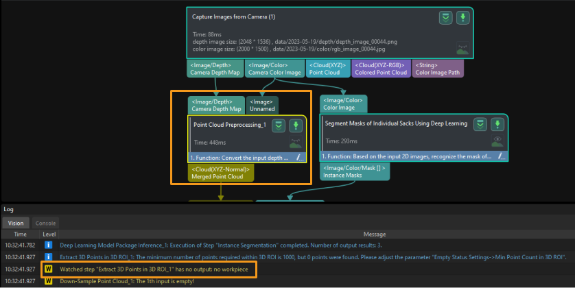
Problem 2: No Output from “Deep Learning Model Package Inference” Step
Symptoms
The Segment Masks of Individual Sacks Using Deep Learning Procedure encountered a failure during execution, and the log panel of Mech-Vision displayed a warning message of “Watched step ‘Deep Learning Model Package Inference_1’ has no output.”
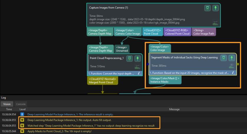
Possible Causes
-
Inappropriate exposure time was set for the capture of 2D images. As shown below, the images from left to right are captured in cases where the exposure time is too long, the exposure time is appropriate, and the exposure time is too short, respectively.

-
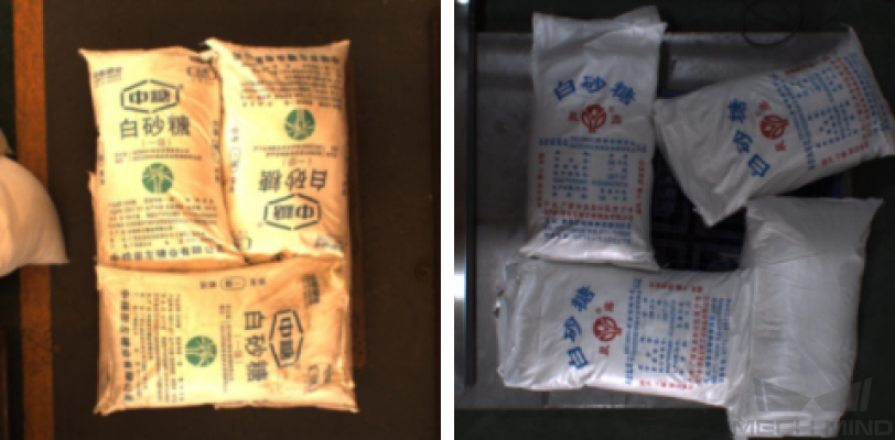
The adjusted white balance was not appropriate for the capture of 2D images. As shown below, the image on the left was captured under incorrect white balance, while the image on the right was captured under correct white balance.
-
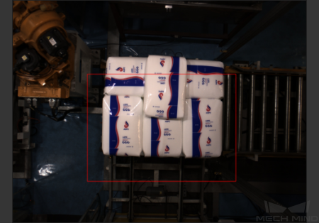
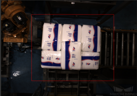
The setting of deep learning recognition region (2D ROI) was inappropriate.
-
Deep learning models demonstrated poor performance for single-case sacks. Therefore, the deep learning models should be improved first.
Solutions
-
Adjust the exposure time of the camera to ensure that the acquired 2D images are normal.
-
Adjust the white balance of the camera. See the documentation of Adjust White Balance.
-
Reset 2D ROI. Make sure that the entire upper surface of the stack are within the 2D ROI that is slightly larger than the full stack, and that the ROI should better not contain any other interfering point clouds.
-
Acquire image data of sacks to iterate deep learning models.
Problem 3: Abnormal Output after Pose Adjustment
Symptoms
The Adjust Poses Procedure encountered a failure during execution, and the log panel of Mech-Vision displayed a message of “Watched step ‘Adjust Poses V2_1’ has no output: pose abnormal.”
Possible Causes
-
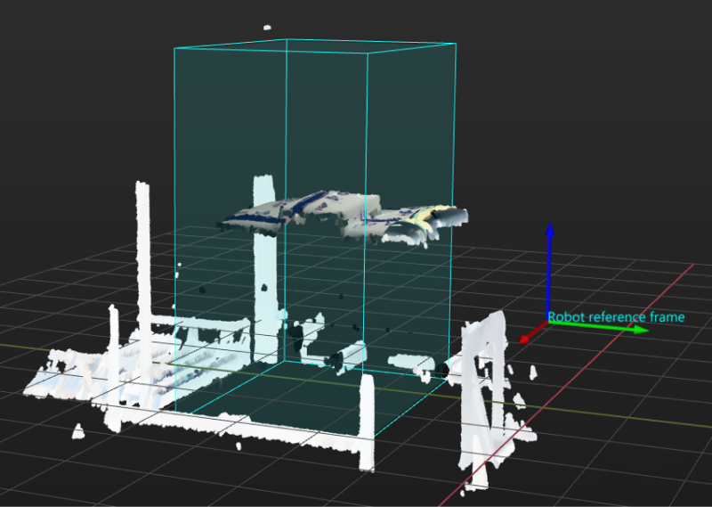
The 3D ROI didn’t cover complete sacks. As a result, the dimensions of the sacks could not be verified in subsequent operations, and no output was obtained from Mech-Vision.
-
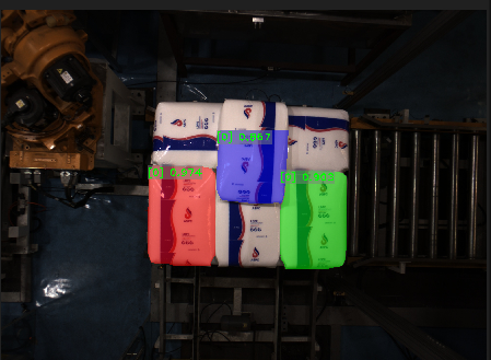
Deep learning models failed to correctly segment masks of individual sacks. As a result, the dimensions of the sacks could not be verified in subsequent operations, and no output was obtained from Mech-Vision.
-
The dimensions input in the Recognize Center Poses of Sacks Procedure differed greatly from recognized ones. Thus, the dimensions of the sacks could not be verified, and no output was obtained from Mech-Vision.

-
Correct poses of sacks were removed, and thus no output could be obtained from Mech-Vision.
Solutions
-
Reset 3D ROI according to workstation layout and pallet pattern dimensions to ensure the sacks are within the ROI.
-
Double-click the Segment Masks of Individual Sacks Using Deep Learning Procedure to view the visualized output from the Deep Learning Model Package Inference Step. If the visualized output demonstrates incomplete sacks or misses some sacks, please refer to Problem 2 for resolution.
-
Measure the sack dimensions and compare them with the input ones. If the difference is huge, you can adjust the parameters of the Read Object Dimensions Step in the Recognize Center Poses of Sacks Procedure to reset the sack dimensions.
-
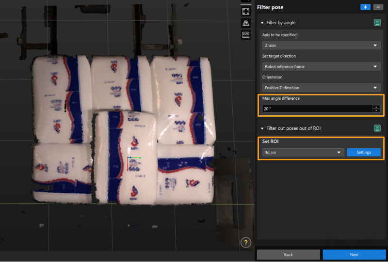
Select the Adjust Poses Procedure and click Open the editor in the Step Parameters panel to adjust poses. Then, click Next in the lower-right corner. Check whether there is any output from the Filter out poses out of ROI Step. (Click
 and check whether the sack poses are output in the visualization area on the left.) If the output is correct, then check whether there is any output from the Filter by angle Step. If sacks are significantly tilted but the poses are correct, you can increase the Max angle difference to a certain extent.
Problem 4: Path Planing Failure Resulting in Collision with Scene Objects
Symptoms
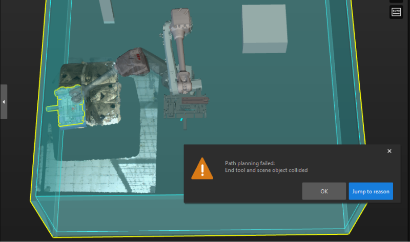
The alert “Path planning failed: End tool and scene object collided” popped up when Mech-Viz was used to run a project.
In the figure below, the air compressed cable extends from the gripper, and the pallet is close to the fence. When the robot attempted to pick sacks near the fence, collisions between the air compressed cable and the fence were often detected, and thus the sacks could not be picked.
Solutions
-
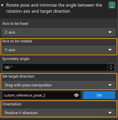
If the gripper is more protruding in the Y-axis of the TCP, for the sack near the fence, the Y-axis of its pose should be adjusted to point to the pallet center. The instructions are as follows:
Select the Adjust Poses Procedure and click Open the editor in the Step Parameters panel to adjust poses. In the default predefined mode, set Orientation to Point to/away from pallet center (depalletizing) and the Application scenario to Point away from, and then set Axis to be rotated to Y-axis. After that, use the manipulator to set the pallet center so that the Y-axis of the sack pose can point to the pallet center.
-
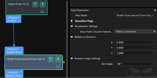
If the gripper is more protruding in the X-axis of the TCP, for the sack near the fence, the X-axis of its pose should be adjusted to point to the pallet center. The instructions are as follows:
Select the Adjust Poses Procedure and click Open the editor in the Step Parameters panel to adjust poses. In the default predefined mode, set Orientation to Point to/away from pallet center (depalletizing) and the Application scenario to Point to, and then set Axis to be rotated to X-axis. After that, use the manipulator to set the pallet center so that the X-axis of the sack pose can point to the pallet center.
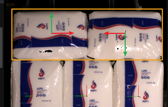
After the above operations are completed, the X-axis or Y-axis of the sack pose will point to the pallet center.
Problem 5: Path Planing Failure Due to Collision between Held Workobject and Point Cloud
Symptoms
Mech-Viz failed to plan a path, and the alert of “Path planning failed: Held workobject and point cloud collided” popped up.
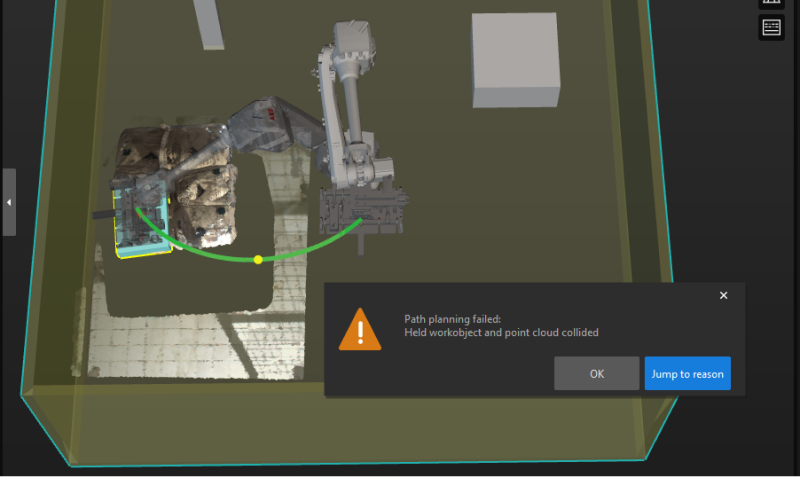
Possible Cause
The problem may be caused by collision, an unreachable waypoint, etc.
If all the poses turn red at the same time, it is much possible that the problem was caused by a point cloud collision.
Solutions
-
In the Vision Move Step, make sure to select the Remove Point Cloud of Target Workobject checkbox under Remove Point Cloud of Target Workobject.

-
In the Vision Move Step, check whether the parameter values of XY-Plane Point Cloud Removal Range Expansion and Z-Direction Point Cloud Removal Range Expansion under Remove Point Cloud of Target Workobject are too small. If so, increase the parameter values appropriately.

Problem 6: Dresspack Wrapping and Excessive Rotation During Path Planning
Symptoms
During path planning in Mech-Viz, the robot encountered problems such as dresspack wrapping and excessive rotation.
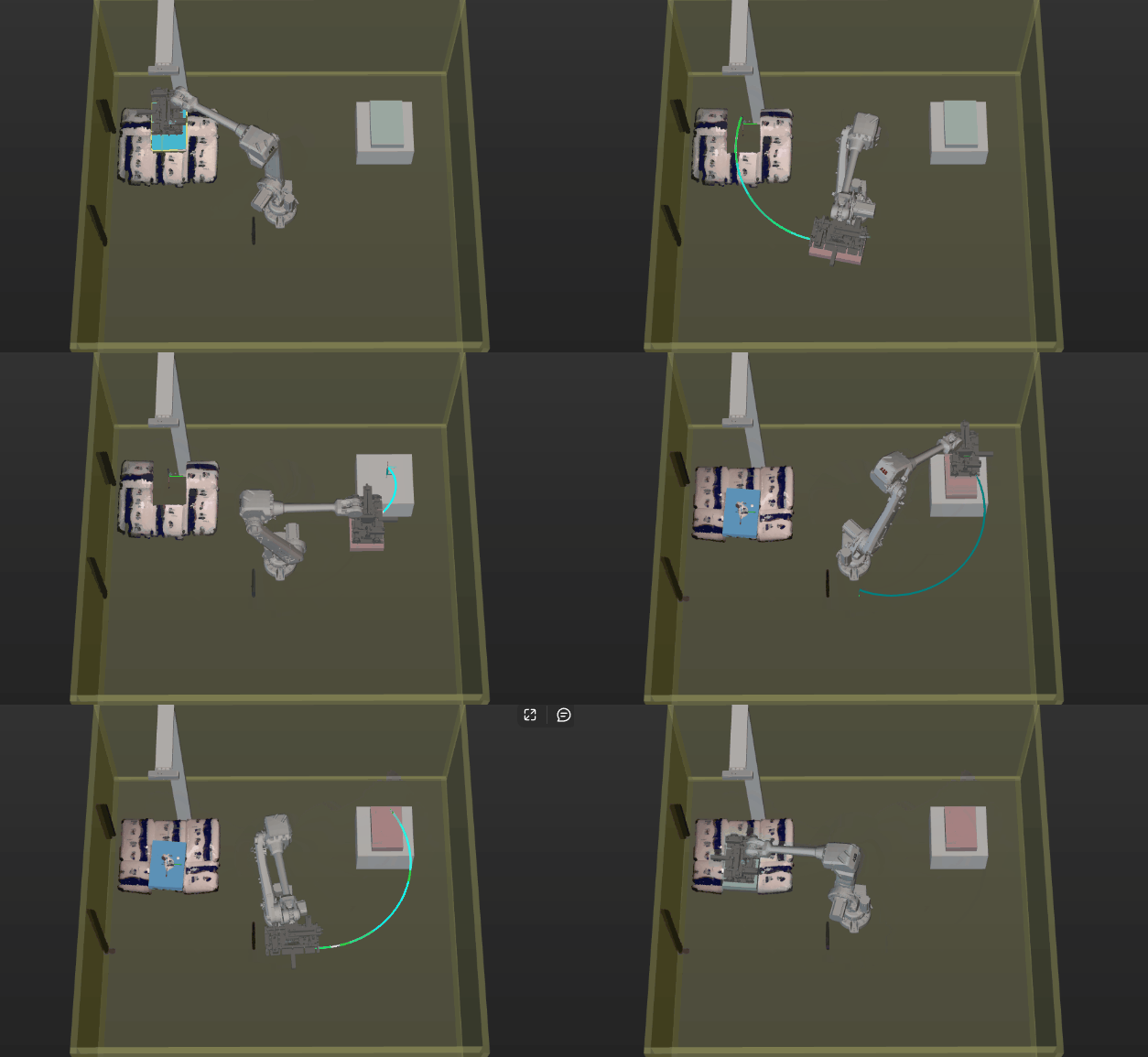
Solutions
-
Adjust the Z-axis of the sack poses to a uniform orientation in the Mech-Vision project.
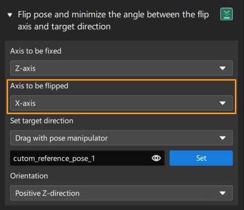
In the custom mode of the pose adjustment tool, add the Flip pose and minimize the angle between the flip axis and target direction option if the sacks are placed transversely or longitudinally. This allows flipping the X or Y-axis of the pose to the target direction, so as to control the rotation angle of the gripper within the range of 0° to 90°.
-
Set soft limits of the robot.
Click Set Soft Limits in the Robot panel of Mech-Viz.

Manually rotate the sixth axis of the real robot, test the limit rotation angle of the sixth axis in the positive and negative directions, and then set the appropriate soft limits with reference to the limit rotation angle of the sixth axis.
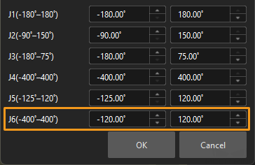
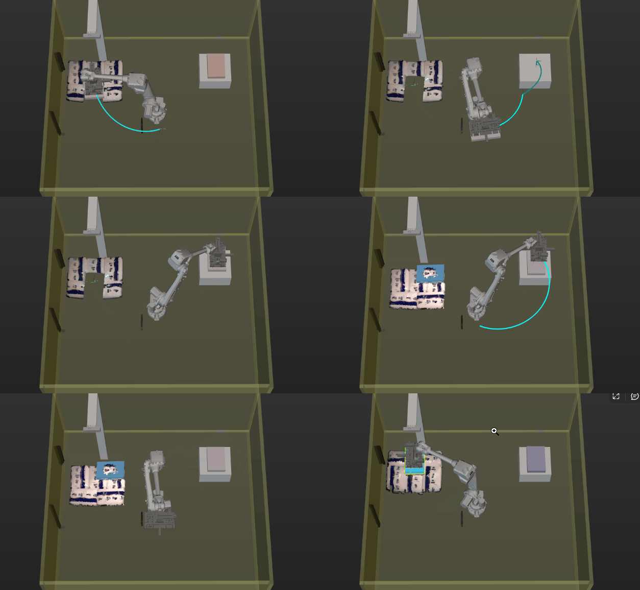
After the above operations, the planned robot picking path is shown as below.
Problem 7: Path Planning Failed Due to Unreachable Waypoints
Symptoms
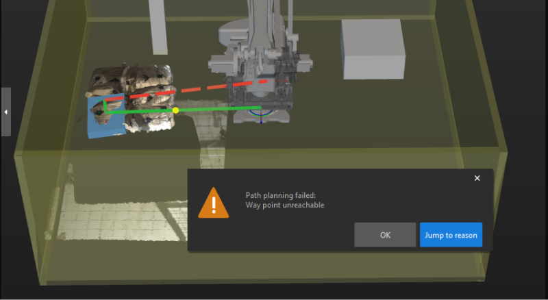
Mech-Viz failed to plan a path, and the alert of “Path planning failed: Way point unreachable” popped up.
For example, when a four-axis robot is used for sack depalletizing, path planning failed due to unreachable waypoints. At this point, you can still manually control the robot to reach any point of the pallet pattern, and the Mech-Vision project can output vision result.
Possible Cause
In most cases, when the incoming sacks are tilted, there may be an included angle between the Z-axis of the sack pose and the Z-axis of the robot reference frame in the X and Y-directions.
For the four-axis robot, its X, Y, and Z-axes can move linearly, and the Z-axis can rotate, i.e., the robot has four degrees of freedom (DOF). When the angle between the Z-axis of the sack pose and that of the robot reference frame is small, Mech-Viz will automatically rectify the Z-axis of the sack pose for picking path planning. When the included angle is large, however, an alert will be triggered, and thus path planning will encounter a failure.
Solution
Rectify the Z-axis of the sack pose before any vision result is output from the Mech-Vision project. Note that before the rectification, judge whether the included angle between the Z-axis of the sack pose and that of the robot reference frame is within the acceptable range. For those sacks with a seriously tilt angle, an alert should be triggered, and the Z-axis of sack poses should not be rectified. Ways to rectify the Z-axis of sack poses are as follows.
-
Add two Rotate Poses’ Axes to Specified Directions under Symmetry Constraints Steps after the Adjust Poses Procedure.
-
Set Axis to Be Rotated to Z and Axis to Be Fixed to X for the first Rotate Poses’ Axes to Specified Directions under Symmetry Constraints Step.
-
Set Axis to Be Rotated to Z and Axis to Be Fixed to Y for the second Rotate Poses’ Axes to Specified Directions under Symmetry Constraints Step.
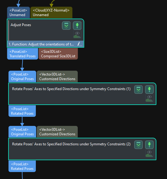
Upon the above parameter setting, the Z-axis of the sack pose can be rectified to be upward in both X and Y-directions.
