Configure Filtering Rules
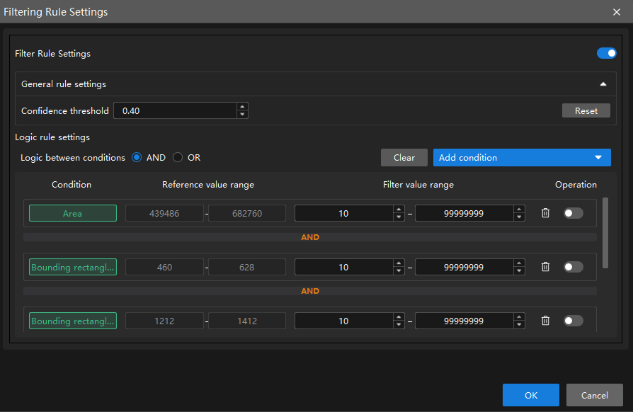
In the Validation tab, click Filtering Rule Settings to configure filtering rules for the model. Once the Filter Rule Settings button is enabled, General rule settings and Logic rule settings can be configured as needed.
|
After the configuration takes effect, validation results change accordingly, and the related settings also take effect in the exported model. |
General Rule Settings
General rule settings is used for basic filtering of inference results. It is recommended to perform preliminary filtering with general rules first, then apply logic rules for refined filtering.
Confidence Threshold
Confidence refers to the accuracy of labeling results. A higher confidence indicates more accurate labeling results. The inference result is retained only when its confidence exceeds this threshold.
You can set the confidence threshold by this step:
Set the threshold according to the actual requirement (default value: 0.4).
| Setting the confidence too high may result in a lower number of displayed labels. |
Logic Rule Settings
Logic rule settings is used for refined filtering of inference results and for setting the logic between multiple added conditions.
Logic Between Conditions
Logic between conditions is used to uniformly set the logic (AND/OR) between conditions for multiple added filtering conditions (such as area, aspect ratio of bounding rectangle, circularity, etc.).
Different condition items are combined according to the Logic between conditions setting (AND/OR); when the same condition item is added multiple times, it is always combined with OR logic, regardless of the Logic between conditions setting.
You can set the logic between conditions by the following steps:
-
Click Add condition and select the filtering condition from the drop-down list.
-
Set the filter value range according to the reference value range, then enable the condition.
-
Set the logic between conditions (AND/OR) as needed.
|
Filter Condition Description
| Condition | Description |
|---|---|
Basic options |
|
Area |
The total number of pixels in a single recognized target region. Used to filter targets that are too large or too small. |
Total area |
The sum of the pixel counts of all recognized targets in the current detection region. Used to control the total coverage of targets and avoid excessive or large-area target clusters. |
Bounding rectangle height |
The height (in pixels) of the axis-aligned bounding rectangle of the target, i.e., the height of the smallest rectangle parallel to the coordinate axes. Used to filter the maximum or minimum vertical span of a target. Suitable for non-tilted or aligned targets; the value may be larger than the actual height for tilted targets. |
Bounding rectangle width |
The width (in pixels) of the axis-aligned bounding rectangle of the target, i.e., the width of the smallest rectangle parallel to the coordinate axes. Used to filter the maximum or minimum horizontal span of a target. Suitable for non-tilted or aligned targets; the value may be larger than the actual width for tilted targets. |
Aspect ratio of bounding rectangle |
The ratio of the longer side to the shorter side of the axis-aligned bounding rectangle of the target. Used to distinguish targets of different shapes, such as distinguishing elongated scratches from round pits. |
Principal axis angle |
The angle (in degrees) between the principal axis of the target and the horizontal direction. Used to filter targets with a specific orientation. |
Advanced options |
|
Circularity |
Measures how close the shape of the target is to a perfect circle. A value closer to 1 indicates a rounder shape. Used to distinguish circular targets (such as screw holes) from irregularly shaped targets (such as cracks and stains). |
Bounding rectangle center X |
The X coordinate of the center of the axis-aligned bounding rectangle. Used to filter the horizontal position of a target in the image. |
Bounding rectangle center Y |
The Y coordinate of the center of the axis-aligned bounding rectangle. Used to filter the vertical position of a target in the image. |
Inradius |
The radius of the largest circle that can be completely contained within the target. Used to evaluate the "solidity" of the target or the minimum through-hole size, and to exclude targets with hollows or that are not compact. |
Circumradius |
The radius of the smallest circle that can completely enclose the target. Used to filter the maximum enclosing size of a target. Commonly used for rough positioning of circular workpieces or upper limit size filtering. |
Inscribed rectangle width |
The width of the largest rectangle that can be completely contained within the target. Used to filter the horizontal dimension of the effective area inside the target and to exclude objects with severe edge damage. |
Inscribed rectangle height |
The height of the largest rectangle that can be completely contained within the target. Used to filter the vertical dimension of the effective area inside the target and to exclude objects with severe edge damage. |
Centroid X |
The horizontal position of the grayscale or geometric centroid of the target region in the image coordinate system. Compared to the geometric center, it better reflects the position of the actual core. Used to filter targets that appear in a specific horizontal region of the image. |
Centroid Y |
The vertical position of the grayscale or geometric centroid of the target region in the image coordinate system. Compared to the geometric center, it better reflects the position of the actual core. Used to filter targets that appear in a specific vertical region of the image. |
Bounding rectangle top-left X |
The X coordinate of the top-left corner of the axis-aligned bounding rectangle of the target. Used to filter the starting horizontal position of a target in the image. |
Bounding rectangle top-left Y |
The Y coordinate of the top-left corner of the axis-aligned bounding rectangle of the target. Used to filter the starting vertical position of a target in the image. |
Bounding rectangle bottom-right X |
The X coordinate of the bottom-right corner of the axis-aligned bounding rectangle of the target. Used to filter the ending horizontal position of a target in the image. |
Bounding rectangle bottom-right Y |
The Y coordinate of the bottom-right corner of the axis-aligned bounding rectangle of the target. Used to filter the ending vertical position of a target in the image. |
Rotated bounding rectangle width |
The width (in pixels) of the minimum-area bounding rectangle of the target, which can be rotated to any angle. It fits the actual shape of the target more closely. Suitable for filtering the width of tilted targets. |
Rotated bounding rectangle height |
The height (in pixels) of the minimum-area bounding rectangle of the target, which can be rotated to any angle. It fits the actual shape of the target more closely. Suitable for filtering the height of tilted targets. |
|
An axis-aligned bounding rectangle is the smallest enclosing rectangle whose four sides are parallel to the image coordinate axes (horizontal/vertical directions). |
After completing the configuration, click OK to make the configuration take effect.