Introduction to Labeling Tools
You can use labeling tools to label the images and hence provide data for deep learning training.
| Please create labels of corresponding classes according to the needs of the current project before using labeling tools. |
Polygon Tool
The Polygon Tool can draw polygon labels with more vertices, which is suitable for objects of complex shapes.
-
Click the Polygon Tool icon
 (or press P on the keyboard).
 -
Click the first position (vertex) in the selection region, then click the second one, third one, etc., to draw the labels, and right-click to finish. (At least three vertices are required.)
-
If multiple label classes are created, colors corresponding to different label classes should be selected.
Ellipse Tool
Use more vertices to make elliptical selections. This tool is suitable for elliptical objects.
-
Right-click the Polygon Tool icon
and then click the Ellipse Tool icon  (or press L on the keyboard).
 -
Long press the left mouse button in the selection region, move it in any direction, and then release the left mouse button to finish the ellipse selection.
-
If multiple label classes are created, colors corresponding to different label classes should be selected.
Rectangle Tool
The Rectangle Tool can be used to draw rectangular labels, which is suitable for rectangular objects.
-
Right-click the Polygon Tool icon
and then click the Rectangle Tool icon  (or press R on the keyboard).
 -
Long press the left mouse button in the selection region, move it in any direction, and then release the left mouse button to finish the rectangular selection.
-
If multiple label classes are created, colors corresponding to different label classes should be selected.
Smart Labeling Tool
The Smart Labeling Tool can be used to automatically select the objects in the image. When multiple objects in an image have large color differences and are scattered, you can use the Smart Labeling Tool to conveniently label the objects in the image.
Currently, the Smart Labeling Tool can work in two modes, and it will automatically switch between them according to the actual situation. Users do not need to manually select a mode.
-
Standard mode (GPU): In this mode, the Smart Labeling Tool has robust labeling capabilities. This tool will automatically switch to the standard mode if the running device has a GPU, with available GPU memory of at least 2.5 GB, and there is no project undergoing training or validation.
-
Lite mode (CPU): In this mode, the Smart Labeling Tool has basic labeling capabilities. This tool will automatically switch to the lite mode if the running device has no GPU, or the available GPU memory is less than 2.5 GB, or there is a project undergoing training or validation.
Steps
-
Click the Smart Labeling Tool icon
 (or press A on the keyboard).
 -
Move the cursor in the selection region and then click the object to be labeled.
-
If the selection cannot completely cover the object, click the uncovered part to expand the selection area.
-
If the selection covers the areas outside the object, right-click these areas to reduce the selection area.
-
-
Click Apply in the upper-left corner of the selection region.
|
When the objects differ greatly in colors and have clear contours, it is recommended that you label multiple objects at a time and click Apply. If the objects are not obviously distinct, it is recommended to label one at a time. |
Labeling Settings
You can click the settings icon  in the upper-left corner of the selection region to configure parameters for the Smart Labeling Tool. The smart labeling settings take effect for labels that are created after the settings are confirmed.
-
Contour vertex density: Specifies the density of vertices on the contour. Valid values: Standard and Sparse.
-
Standard: Generates more vertices for labels, providing higher precision when manually fine-tuning the contour.
-
Sparse: Generates fewer vertices for labels, suitable for objects with regular shapes that do not require fine-tuned labeling.
-
Pre-trained Labeling Tool
After you validate a model, you can import new image data to the current module and use the pre-trained labeling feature to perform auto-labeling based on this model.
| The pre-trained labeling feature is available only when the current module contains validated models. |
The Pre-trained Labeling Tool can be used only on the following two types of data:
-
Unlabeled data
-
Automatically labeled data (images with a yellow triangle at the front of the image number)
|
|
The pre-trained labeling feature can significantly reduce the cost of manual labeling. However, the accuracy of the results depends on the model that you use. We recommend that you train a high precision model before you use the pre-trained labeling feature. |
You can use the Pre-trained Labeling Tool in one of the following three methods:
-
Method 1: Pre-trained labeling button
-
On the upper part of the image list, click the Pre-trained labeling button. All images in the image list will be labeled by using the Pre-trained Labeling Tool.
-
After the labeling process is finished, you can view a yellow triangle in the upper left corner of the sequence number of the labeled images.
-
-
Method 2: Pre-trained labeling option
-
In the image list, select one or more images that you need to label.
-
Right-click the images and select Pre-trained labeling, the labeling process starts. After the labeling process is finished, you can view a yellow triangle in the upper left corner of the sequence number of the labeled images.
-
-
Method 3: Pre-trained Labeling Tool
-
In the labeling toolbar, right-click the Smart Labeling Tool icon
, and then click the Pre-trained Labeling Tool icon  (or press D on the keyboard).
 -
On the upper part of the image, click Start labeling, and the Pre-trained Labeling Tool will start to label the image. After the labeling process is finished, you can view a yellow triangle in the upper left corner of the sequence number of the image.
-
|
Labeling Settings
You can click the settings icon in the upper-left corner of the selection area to configure parameters for the Pre-trained Labeling Tool. The pre-trained labeling settings take effect for labels that are created after the settings are confirmed.
-
Contour vertex density: Specifies the density of vertices on the contour. Valid values: Standard and Sparse.
-
Standard: Generates more vertices for labels, providing higher precision when manually fine-tuning the contour.
-
Sparse: Generates fewer vertices for labels, suitable for objects with regular shapes that do not require fine-tuned labeling.
-
VFM Labeling Tool
Mech-DLK incorporates the visual foundation models (VFMs) developed by Mech-Mind. You can use the VFM Labeling Tool powered by the VFMs to quickly label datasets.
The VFM Labeling Tool can be used only on the following two types of data:
-
Unlabeled data
-
Automatically labeled data (images with a yellow triangle at the front of the image number)
|
You can use the VFM Labeling Tool in one of the following three methods:
-
Method 1: VFM labeling button
-
On the upper part of the image list, click the VFM labeling button. All images in the image list will be VFM-labeled.
-
After the labeling process is finished, you can view a yellow triangle in the upper left corner of the sequence number of the labeled images.
-
-
Method 2: VFM labeling option
-
In the image list, select one or more images that you need to label.
-
Right-click the images and select VFM labeling, the labeling process starts. After the labeling process is finished, you can view a yellow triangle in the upper left corner of the sequence number of the labeled images.
-
-
Method 3: VFM Labeling Tool
-
In the labeling toolbar, right-click the Smart Labeling Tool icon
, and then click the VFM Labeling Tool icon  (or press S on the keyboard).
 -
On the upper part of the image, click Start labeling, and the VFM Labeling Tool will start to label the image. After the labeling process is finished, you can view a yellow triangle in the upper left corner of the sequence number of the image.
-
After the labeling is completed, Mech-DLK will generate a label class named "model_label" for the labels created by the VFMs.
If you want to modify VFM Labeling Settings, please follow these steps:
-
In the labeling toolbar, right-click the Smart Labeling Tool icon
, and then click the VFM Labeling Tool icon . -
Click the settings icon
on the upper area of the selection area. -
In the window of VFM Labeling Settings, you can modify the VFM labeling results.
Labeling Settings
You can click the settings icon in the upper-left corner of the selection region to configure parameters for the VFM Labeling Tool. The VFM labeling settings take effect for labels that are created after the settings are confirmed.
-
Contour vertex density: Specifies the density of vertices on the contour. Valid values: Standard and Sparse.
-
Standard: Generates more vertices for labels, providing higher precision when manually fine-tuning the contour.
-
Sparse: Generates fewer vertices for labels, suitable for objects with regular shapes that do not require fine-tuned labeling.
-
-
Label confidence: Filters labels with confidence higher than this value. Confidence indicates the accuracy of the labeling results. The higher the confidence, the more accurate the labeling results are.
Setting the confidence too high may result in a lower number of displayed labels. -
Max num of labeling objects: Specifies the maximum number of labels.
Template Tool
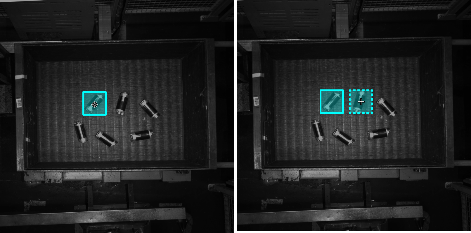
You can use the Template Tool to set an existing selection as a template. After setting, you can use this template to rapidly label contours and objects with the same pose.
It is suitable for scenarios where there are multiple neatly arranged objects of the same type in an image, which can improve labeling efficiency.
-
Click the Template Tool icon
 (or press C on the keyboard).
 -
Click the region that needs to be set as the template.
-
Move the template to the object that you need to select, adjust the angle of the template to make it fit the object, and then click it.
-
Coarse adjustment: Press and hold the Shift key and then scroll the mouse wheel.
-
Fine adjustment: Adjust the Rotation angle parameter.
-
| During labeling, press and hold the Ctrl key and click the selection to switch the template. You can also click Replace template and then click the selection to achieve the same purpose. |
Mask Tool
If there are some irrelevant parts that may interfere with model training, you can use the Mask Tool to cover such parts. The masked parts will not be involved in training. It is recommended to set a distinct color for the mask.
The Mask Tool supports different mask modes. You can choose whether the mask takes effect only on the current image or on all images as required.
You can choose among the following three mask tools built in the software according to actual needs.
Mask Polygon Tool
-
Click the Mask Polygon Tool icon
 (or press Shift + P on the keyboard).
 -
Set “Fill” for the mask.
-
Click the first position (vertex) in the selection area, then click the second one, third one, etc., to draw the labels, and right-click to finish.
Mask Brush Tool
-
Right-click the Mask Polygon Tool icon
, and then click the Mask Brush Tool icon  (or press Shift+B on the keyboard).
 -
Set the “Fill” of the mask and adjust the slider to determine the brush size.
-
Press and hold the left mouse button in the selection area, move in any direction, and then release the left mouse button to finish the drawing.
Mask Lasso Tool
-
Right-click the Mask Polygon Tool icon
, and then click the Mask Lasso Tool icon  (or press Shift+N on the keyboard).
 -
Set “Fill” for the mask.
-
Press and hold the left mouse button in the selection area and move in any direction to form closed shapes with the starting point.
Mask Mode
Mask modes are divided into Single image mask and Global mask.
-
Single image mask: The mask is only valid in the current image.
You can copy and paste single image masks by following the steps below.
-
Use the Mask Tool to draw a single image mask.
-
Click the Select Tool icon
 (or press F on the keyboard).
 -
In the labeling region, right-click the mask to be copied and click Copy (or press Ctrl+C on the keyboard); in the target image, right-click and select Paste (or press Ctrl + V on the keyboard). You can also select multiple target images in the image list, right-click and select Paste Mask(s) to paste them in batches.
-
-
Global mask: The mask applies to all images.
Eraser Tool
Mask Eraser Tool
The Mask Eraser Tool can be used to erase the masks.
Polygon Mask Eraser Tool
-
Click the Polygon Mask Eraser Tool icon
 (or press Ctrl+Alt+P on the keyboard).
 -
Click the first position (vertex) in the selection area, then click other positions, and finally right-click to complete the drawing to erase the masks within the polygon area.
Brush Mask Eraser Tool
-
Right-click the Polygon Mask Eraser Tool icon
, then select the Brush Mask Eraser Tool icon  (or press Ctrl+Alt+B on the keyboard).
 -
Press and hold the left mouse button in the selection area and drag in any direction to erase the masks along the drag path. You can set the Brush shape to Round or Square and adjust the brush size using the slider.
Lasso Mask Eraser Tool
-
Right-click the Polygon Mask Eraser Tool icon
, then select the Lasso Mask Eraser Tool icon  (or press Ctrl+Alt+N on the keyboard).
 -
Press and hold the left mouse button in the selection area and drag in any direction until the path forms a closed shape, then release the button to erase the masks within the enclosed area.
|
For modules that support Single image mask and Global mask, the Mask Eraser Tool can only erase masks drawn in the current mask mode. To batch clear single image masks, select one or more images in the image list, then right-click and select Clear Single Image Mask(s). |
ROI Tool
You can use the ROI Tool to set the region of interest.
Setting the ROI can avoid interferences from the background.
-
Click the ROI Tool icon
 (or press O on the keyboard).
 -
Adjust the ROI frame in the selection region.
-
Click the application icon
 in the lower-right corner of the ROI to apply the current ROI or click the close icon
  to disable the ROI Tool.
 -
Click the Reset button in the upper left corner of the image to reset the ROI.
Select Tool
The Select Tool supports coarse and fine-tuning labeling.
-
Roughly adjust labeling
You can use the Select Tool to zoom, select, move, resize, rotate, etc.:
-
In the labeling toolbar, click the Select Tool icon
(or press F on the keyboard). -
You can perform operations such as scaling, selecting, moving, and roughly adjusting labels:
-
Place the cursor in the selection area of the image and use the mouse wheel to scroll forward to zoom in and scroll backward to zoom out.
-
Move the cursor in the selection region and then click the selections to be processed. Select multiple selections by pressing and holding the Ctrl key.
-
Right-click and drag in the selection area to select all labels within the selected area.
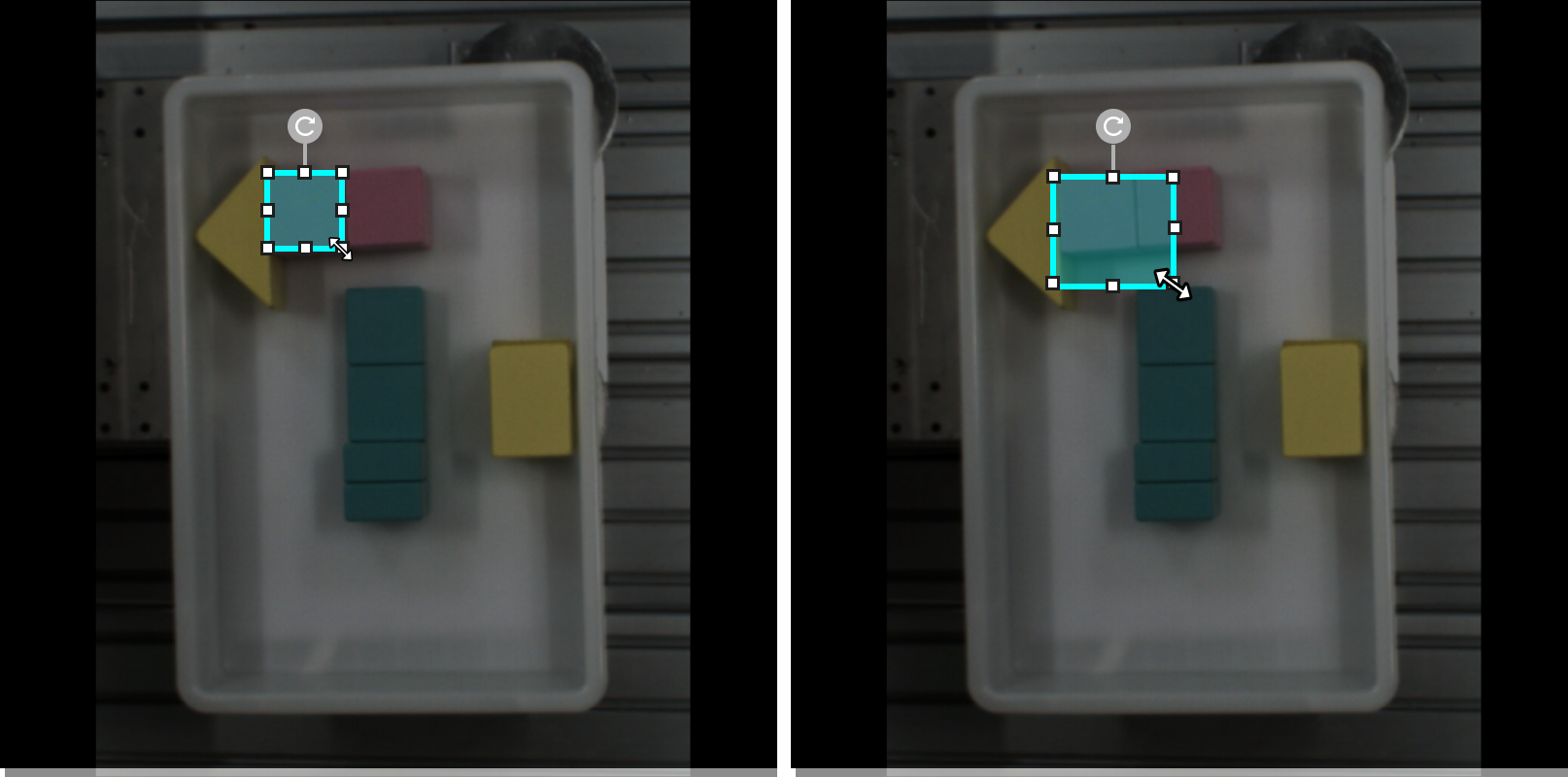
Adjust size
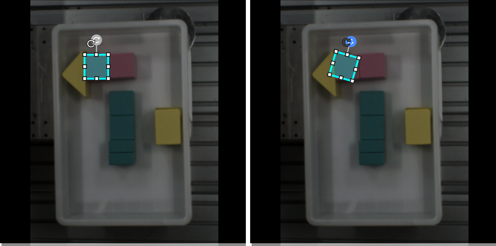
Rotation
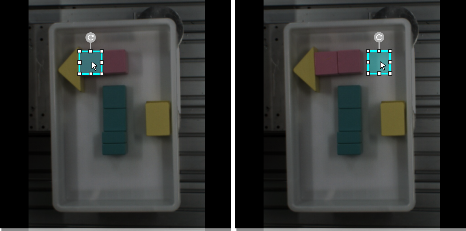
Move
-
-
-
Finely fine-tune labeling contours
When the labeling is completed and the vertices cannot be adjusted directly, you can use the Select Tool to fine-tune the label:
-
In the labeling toolbar, click the Select Tool icon
(or press F on the keyboard) to select the label to be adjusted. -
Adjust the contour in one of the following three ways according to actual situation. Please ensure that the selected area closely aligns with the object contour.
-
Place the mouse cursor on a vertex of the contour. When the cursor turns into the hand cursor
 , long-press the left mouse button and drag the vertex to adjust the contour.
 -
Place the mouse cursor on a vertex of the contour. When the cursor turns into the hand cursor
, click the right mouse button to delete the vertex. -
Place the mouse cursor on the contour. When the cursor turns into the cross cursor
 , click the left mouse button to add a vertex.
-
-