Use the Object-Bin Segmentation Module
Based on the Object-Bin Segmentation general model (click here to download). This topic will show you how to use the Object-Bin Segmentation module to train a model that can segments the target objects and the bin.
The overall process includes five steps: preparation, data labeling, model training, model validation, and model export.
| You can also use your own data. The overall workflow is the same, but the labeling stage is different. |
Preparation
-
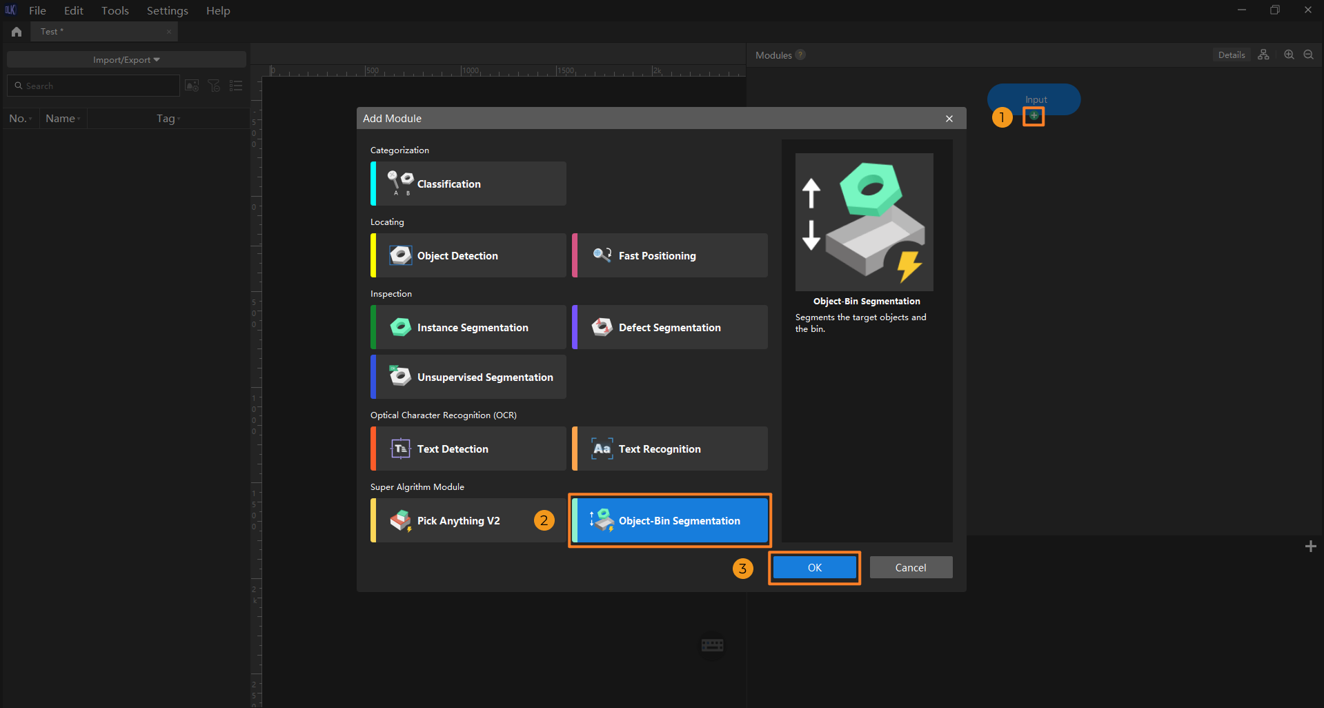
Create a new project and add the Object-Bin Segmentation module: Open Mech-DLK, click New Project in the interface, name the project, and select a directory to save the project. In the main interface, click the + button under the Input module, and select the Object-Bin Segmentation module in the Add Module window.
-
Import general model package: In the pop-up Add General Model Package window, click the Select File button, select the model package file to import, and then click OK.
If the Object-Bin Segmentation general model package is not available locally, click the download link to download it from Download Center. 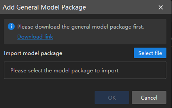
-
Import image data: Import the acquired image data. You can use one of the following methods to import image data:
-
Method one
Drag and drop images or files into the image list area to import them. Importing datasets by dragging is not supported.
-
Method two
On the top of the image list, click the Import/Export button. Select the import method based on the data type:
-
Import from Previous Module: Import images from the previous module.
-
Import Images: Import one or more images.
-
Import Folder: Import all images in the folder (images in the subfolders are not included).
-
Import Dataset: Import datasets in the DLKDB format (.dlkdb), which are datasets exported from Mech-DLK.
-
-
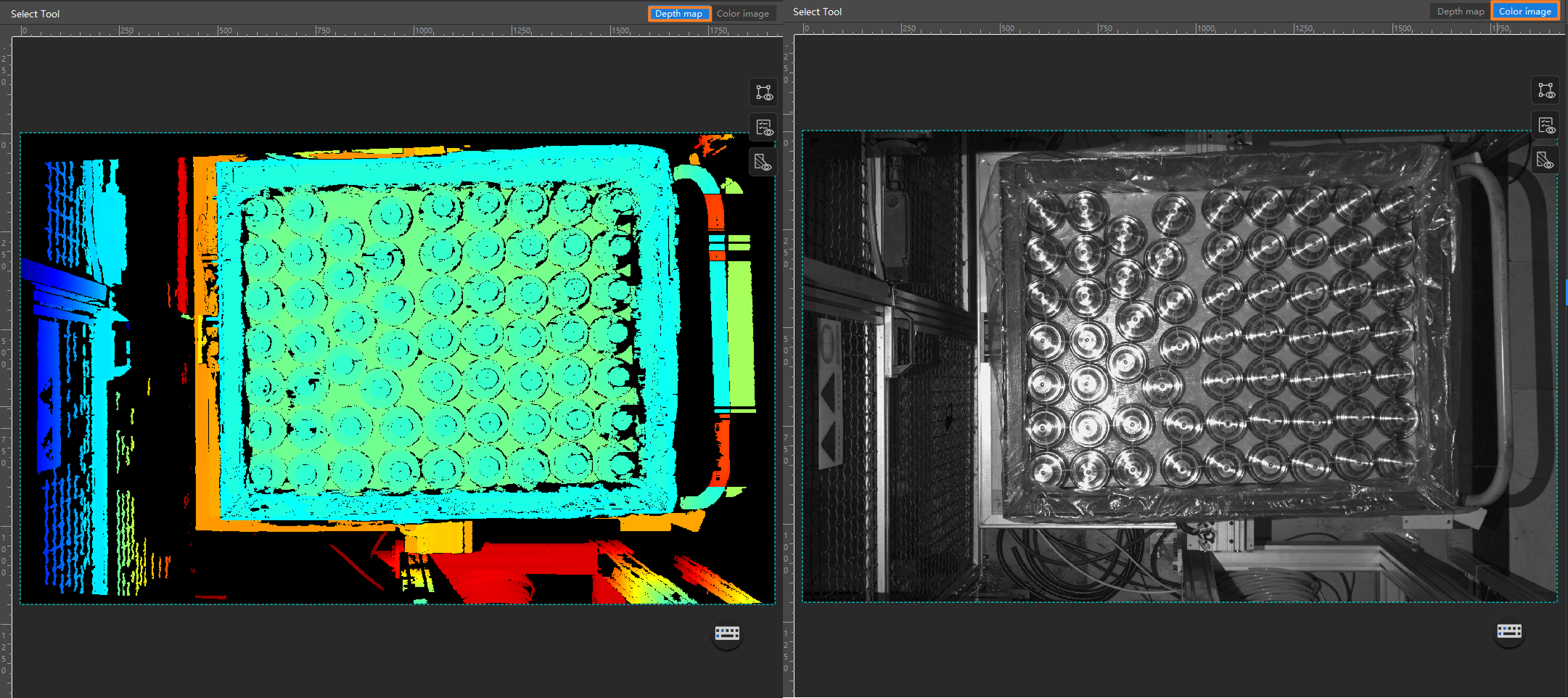
When using the Object-Bin Segmentation module, the depth map and color image should be imported simultaneously. Please make sure that the two image folders are in the same directory, and the image files correspond and are of the same size. When importing any type of image, the system automatically imports the corresponding image of the other type.
-
The Input module can preprocess images for depth maps and color images separately. The preprocessing configuration takes effect for all images.
After the images are imported successfully, you can view the image results by switching Depth map and Color image buttons in the visualization area.
-
-
Select an ROI: Click the ROI tool icon
 and adjust the frame to select the bin in the image as an ROI. Then, click the application icon
  in the lower right corner of the ROI to save the setting. Setting the ROI can avoid interferences from the background.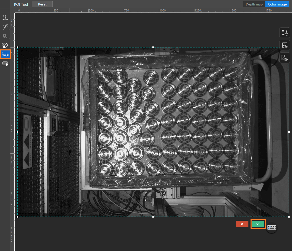
Data Labeling
Please strictly follow the Data Labeling Standard when labeling.
-
Labeling rules: By default, the object-Bin Segmentation module supports two labeling classes: Bin and Object. Custom labeling classes are not supported.
Press and hold the Ctrl key and scroll the mouse wheel up to zoom in on the image for more precise labeling. -
Labeling data: use the Pre-trained Labeling Tool and Polygon Tool to label data. It is recommended to label all objects first and then the bin.
-
In the labeling toolbar, right-click the smart labeling tool icon
 , select the pre-trained labeling tool, and then click Start Labeling.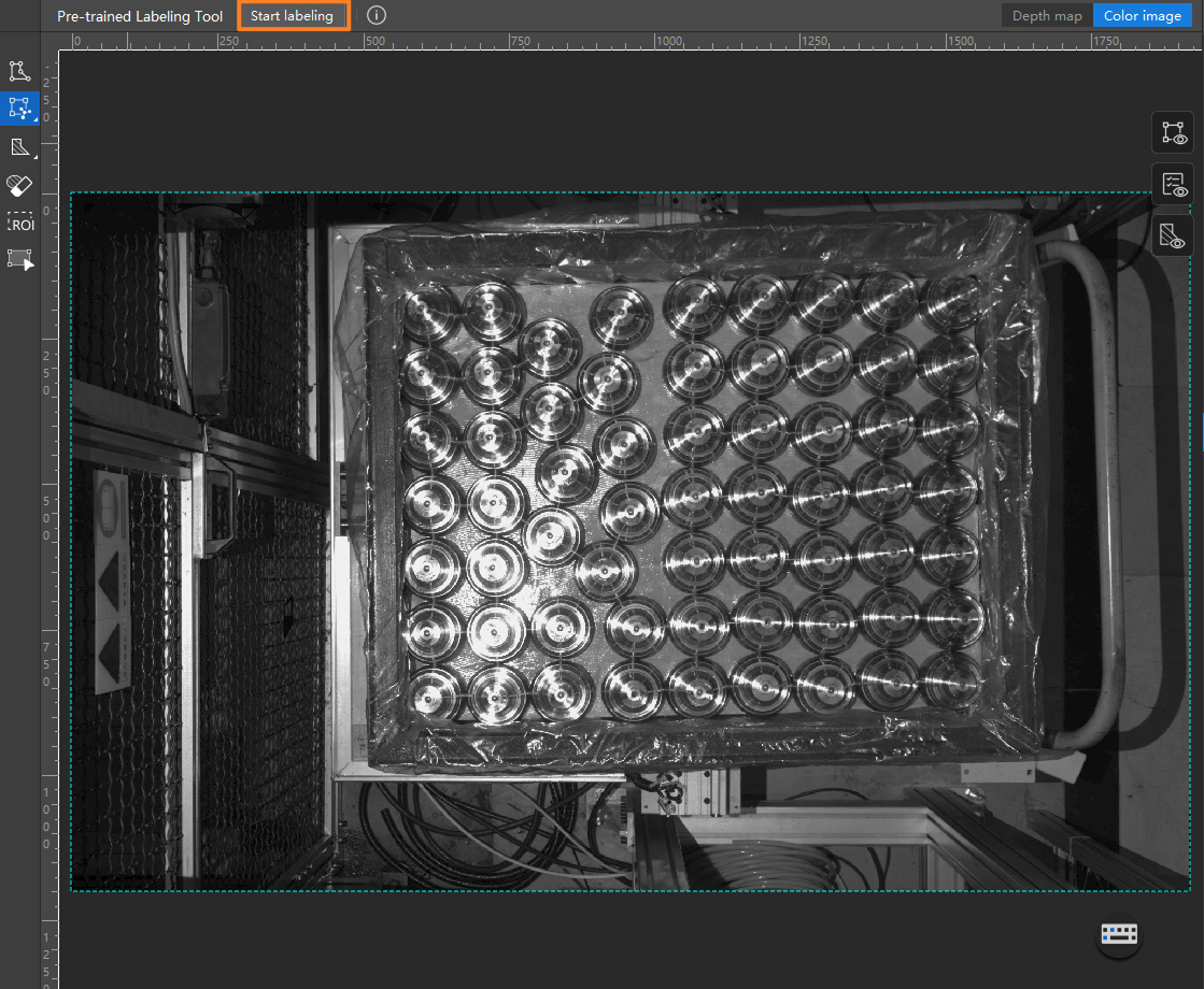
-
After you finish the initial labeling, click the polygon tool icon
 to further draw on and make local adjustments to the labeling results.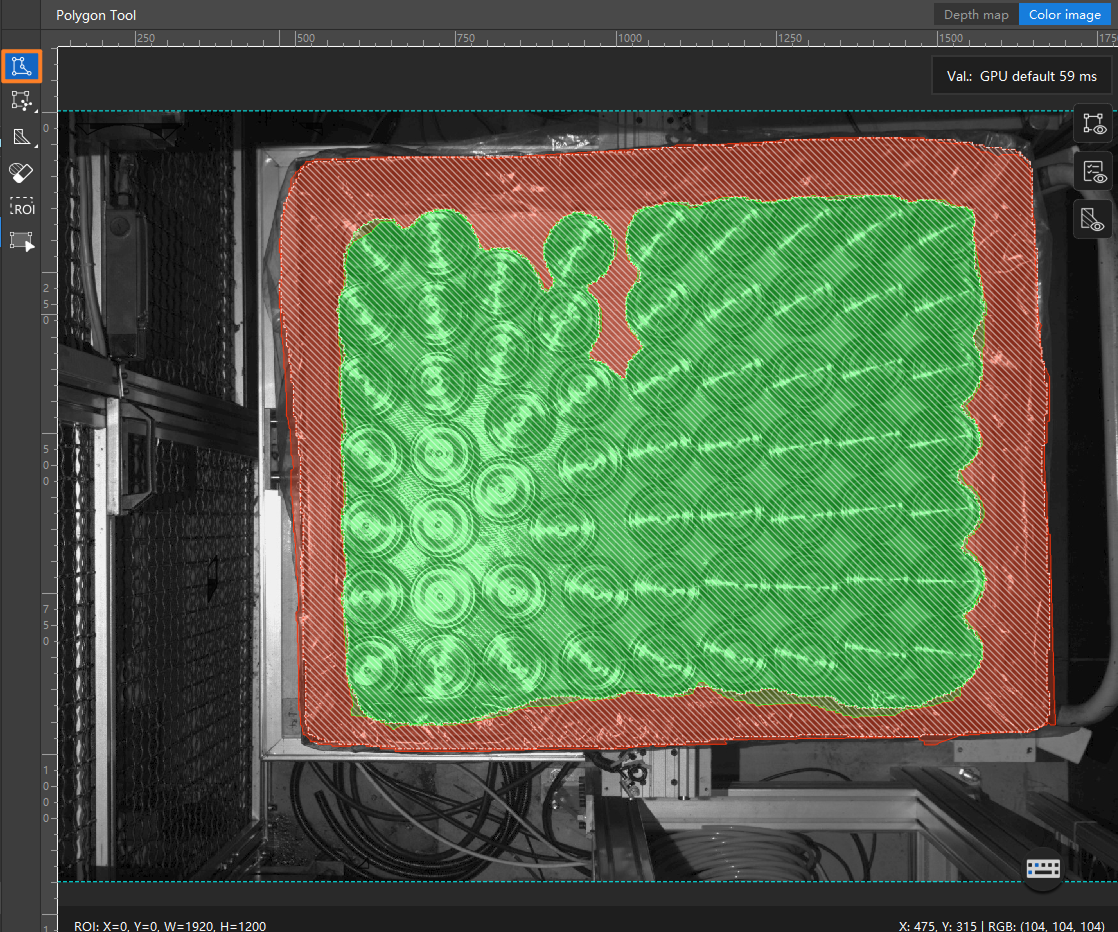
Please select the appropriate labeling tool according to the actual scenario. For more information about how to use labeling tools, see Introduction to Labeling Tools. -
-
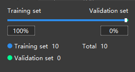
Split training and validation sets: Move labeled images to the training set and split them for training and validation. Typically, 80% of the data is allocated for training and 20% for validation in common scenarios. The software will automatically split the labeled images that have been moved to the training set into 80% for training and 20% for validation. The validation set is not required during training in this module.
Model Training
-
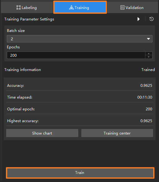
Train the model: In the Training tab, set training parameters and click Train to start training the model. Usually, the default training parameters are sufficient. If you need to adjust parameters, please refer to Parameter Description.
-
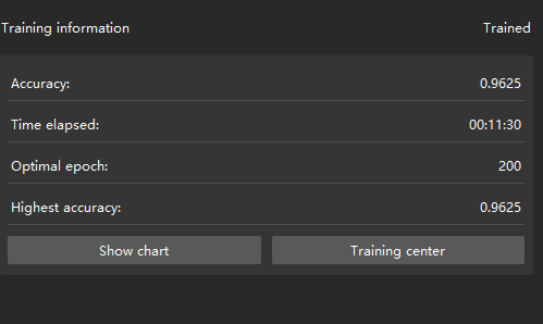
Monitor training progress through training information: On the Training tab, the training information panel allows you to view real-time model training details.
-
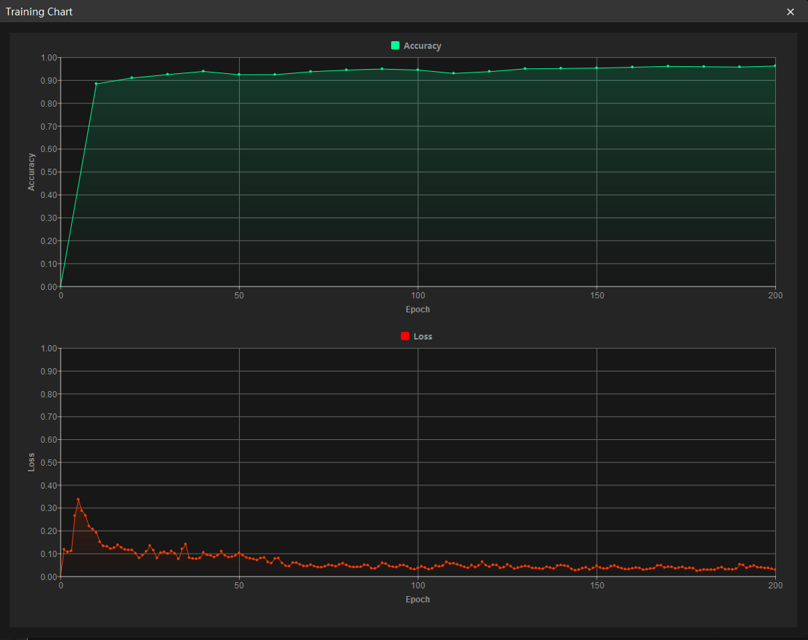
View training progress through the Training Chart window: Click the Show chart button under the Training tab to view real-time changes in the model’s accuracy and loss curves during training. An overall upward trend in the accuracy curve and a downward trend in the loss curve indicate that the current training is running properly.
Model Validation
-
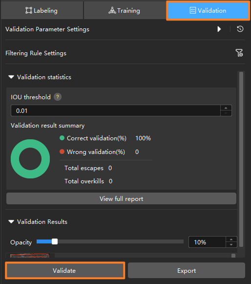
Validate the model: After training is completed or manually stopped, click the Validate button under the Validation tab to validate the model.
-
Check the model’s validation results in the training set: After validation is complete, you can view the validation result summary in the Validation statistics section under the Validation tab.
-
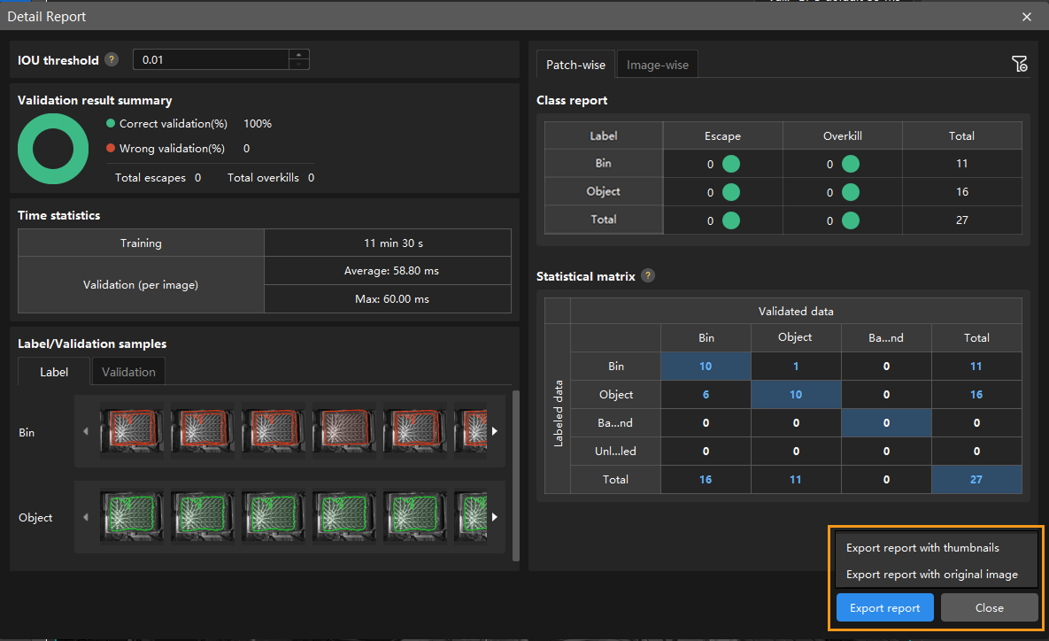
Click the View full report button to open the Detailed Report window for detailed validation statistics.
-
The Statistical matrix in the report shows the correspondence between the validated data and labeled data of the model, allowing you to assess how well each class is matched by the model.
-
In the matrix, the vertical axis represents labeled data, and the horizontal axis represents predicted results. Blue cells indicate matches between predictions and labels, while the other cells represent mismatches, which can provide insights for model optimization.
-
Clicking a value in the matrix will automatically filter the image list in the main interface to display only the images corresponding to the selected value.
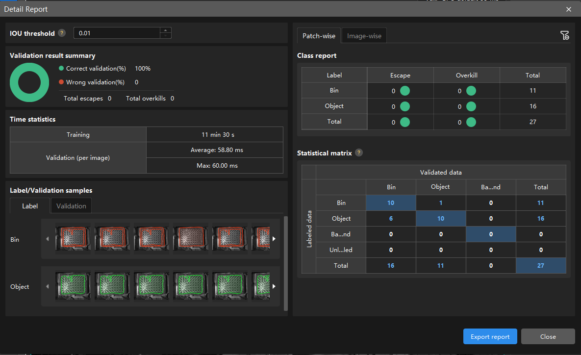
If the validation results on the training set show missed or incorrect detections, it indicates that the model training performance is unsatisfactory. Please check the labels, adjust the training parameter settings, and restart the training. You can also click the Export report button at the bottom-right corner of the Detailed Report window to choose between exporting a thumbnail report or a full-image report.
You don’t need to label and move all images with missed or incorrect detections in the test set into the training set. You can add labels to a portion of the images and include them in the training set to retrain and validate the model. Use the remaining images as a reference to observe the validation results and assess the performance of the model iteration. -
-
Restart training: After adding newly labeled images to the training set, click the Train button to restart training.
-
Recheck model validation results: After training is complete, click the Validate button again to validate the model and review the validation results on each dataset.
-
Continuously optimize the model: Repeat the above steps to continuously improve model performance until it meets the requirements.
Model Export
Click the Export button. In the pop-up dialog box, select a directory to save the exported model, and click Export.
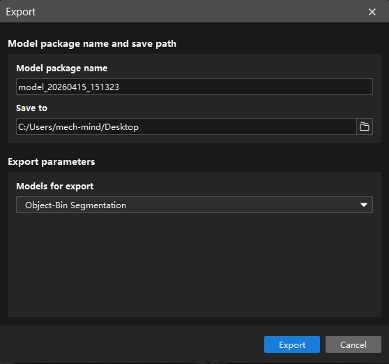
The exported model can be used in Mech-Vision. Click here to view the details.