Solution Deployment
This section introduces the deployment of the Square Steel Billets vision solution. The overall process is shown in the figure below.
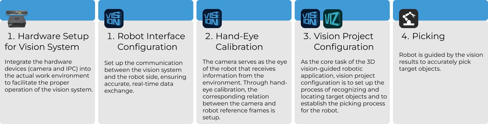
Vision System Hardware Setup
Vision system hardware setup refers to integrating the hardware (camera and industrial PC) into the actual environment to support the normal operation of the vision system.
In this phase, you need to install and set up the hardware of the vision system. For details, refer to Vision System Hardware Setup.
Robot Communication Configuration
Before robot communication configuration, it is necessary to obtain the solution first. Click here to see how to obtain the solution.
-
Open Mech-Vision.
-
In the Welcome interface of Mech-Vision, click Create from Solution Library to open the Solution Library.
-
Enter the Typical cases category in the Solution Library, click the
 icon in the upper right corner for more resources, and then click the Confirm button in the pop-up window.
 -
After acquiring the solution resources, select the Square Steel Billets solution under the Randomly-stacked part picking category, fill in the Solution name and Path at the bottom, and finally click the Create button. Then, click the Confirm button in the pop-up window to download the Square Steel Billets solution.
Once the solution is downloaded, it will be automatically opened in Mech-Vision.
Before deploying a Mech-Mind vision solution, you need to set up the communication between the Mech-Mind Vision System and the robot side (robot, PLC or host computer).
The Square Steel Billets solution uses Standard Interface communication. For detailed instructions, please refer to Standard Interface Communication Configuration.
Hand-Eye Calibration
Hand-eye calibration establishes the transformation relationship between the camera and robot reference frames. With this relationship, the object pose determined by the vision system can be transformed into that in the robot reference frame, which guides the robot to perform its tasks.
Please refer to Robot Hand-Eye Calibration Guide and complete the hand-eye calibration.
|
Every time the camera is mounted, or the relative position of the camera and the robot changes after calibration, it is necessary to perform hand-eye calibration again. |
Vision Project Configuration
After completing the communication configuration and hand-eye calibration, you can use Mech-Vision to configure the vision project.
The process of how to configure a vision project is shown in the figure below.
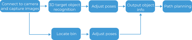
Connect to the Camera and Capture Images
-
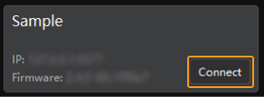
Connect to the camera.
Open Mech-Eye Viewer, find the camera to be connected, and click the Connect button.
-
Adjust camera parameters.
To ensure that the captured 2D image is clear and the point cloud is intact, you need to adjust the camera parameters. For detailed instructions, please refer to LSR L-GL Camera Parameter Reference.
-
Capture images.
After the camera is successfully connected and the parameter group is set, you can start capturing the target object images. Click the
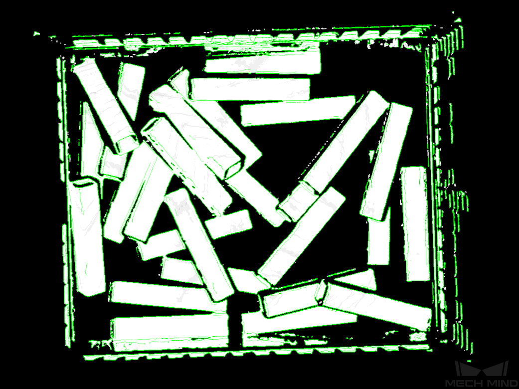
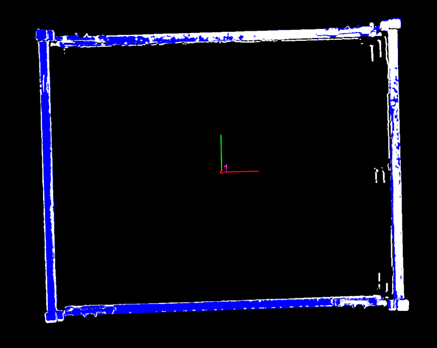
 button on the top to capture a single image. At this time, you can view the captured 2D image and point cloud of the target object. Ensure that the 2D image is clear, the point cloud is intact, and the edges are clear. The qualified 2D image and point cloud of the target object are shown on the left and right in the figure below respectively.
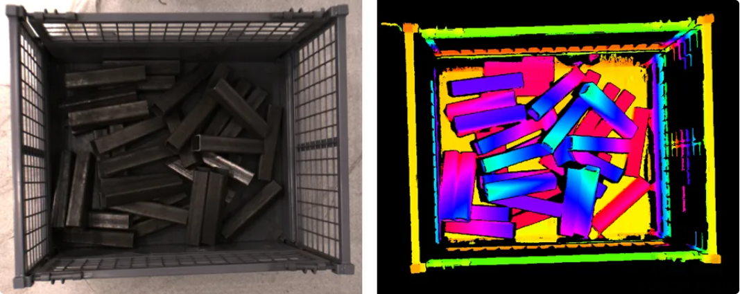
-
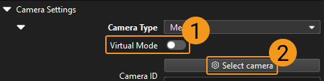
Connect to the camera in Mech-Vision.
Select the Capture Images from Camera Step, disable the Virtual Mode option, and click the Select camera button.
In the pop-up window, click the
 icon on the right of the camera serial number. When the icon turns into
  , the camera is connected successfully. After the camera is connected successfully, you can select the camera calibration parameter group in the drop-down list on the right, as shown below.
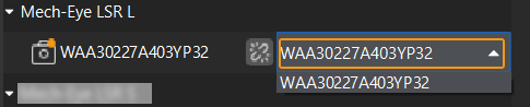
Now that you have connected to the real camera, you do not need to adjust other parameters. Click the
 icon on the Capture Images from Camera Step to run the Step. If there is no error, the camera is connected successfully and the images can be captured properly.
3D Target Object Recognition (to Recognize Target Object)
This solution uses the 3D Target Object Recognition Step to recognize target objects. Click the Config wizard button in the Step Parameters panel of the 3D Target Object Recognition Step to open the 3D Target Object Recognition tool to configure relevant settings. The overall configuration process is shown in the figure below.

Point Cloud Preprocessing
Before point cloud preprocessing, you need to preprocess the data by adjusting the parameters to make the original point cloud clearer, thus improving the recognition accuracy and efficiency.
-
Set an effective recognition area to block out interference factors and improve recognition efficiency.
-
Set the Edge extraction effect, Noise removal level, and Point filter parameters to remove noise.
After point cloud preprocessing, click the Run Step button.
Recognize Target Object
After point cloud preprocessing, you need to create a point cloud model for the target object in the Target Object Editor, and then set matching parameters in the 3D Target Object Recognition tool for point cloud model matching.
-
Create a target object model.
Click the Open target object editor button to open the editor, import the STL file to generate a point cloud model for the target object.
-
Set parameters related to object recognition.
-
Enable Advanced mode on the right side of Recognize target object.
-
Matching mode: Enable Auto-set matching mode. Once enabled, this Step will automatically adjust the parameters under Coarse matching Settings and Fine matching settings.
-
Extra fine matching: Enable extra fine matching to perform a second fine matching with the surface model on the matching result, improving the picking accuracy in the Z-direction.
-
Confidence settings: Set Confidence strategy to Manual, Joint scoring strategy to Consider both surface and edge, and set Surface matching confidence threshold to a high value, such as 0.8, to remove incorrect matching results.
-
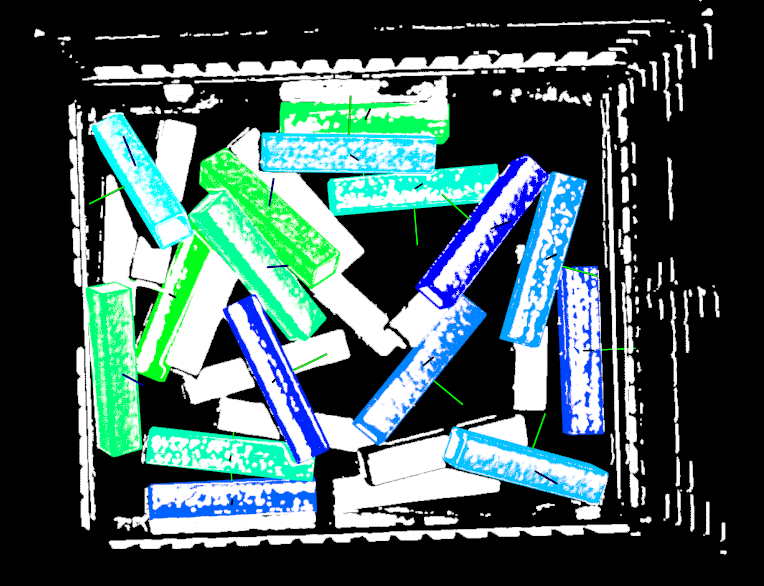
Output—Max outputs: Minimize the number of outputs to reduce matching time, while ensuring that path planning requirements are met. In this solution, the Max outputs parameter is set to 15.
-
Remove coinciding poses and remove overlapped poses: To remove coinciding and overlapping recognition results, enable the Remove poses of coinciding objects and Remove poses of overlapped objects options, and set their respective thresholds to 30% and 20%.
-
After setting the above parameters, click the Run Step button. The matching result is shown in the figure below.
Configure Step Ports
After target object recognition, Step ports should be configured to provide vision results and point clouds for Mech-Viz for path planning and collision detection.
To ensure that objects can be successfully picked by the robot, you need to adjust the object center point so that its Z-axis points upwards. Under Select port, select Port(s) related to object center point, and select the Preprocessed point cloud option. Then click the Save button. New output ports will be added to the 3D Target Object Recognition Step after the settings.
3D Target Object Recognition (to Recognize Bin)
This solution uses the 3D Target Object Recognition Step to recognize the bin. Click the Config wizard button in the Step Parameters panel of the 3D Target Object Recognition Step to open the 3D Target Object Recognition tool to configure relevant settings. The overall configuration process is shown in the figure below.
Point Cloud Preprocessing
Before point cloud preprocessing, you need to preprocess the data by adjusting the parameters to make the original point cloud clearer, thus improving the recognition accuracy and efficiency.
-
Set an effective recognition area to block out interference factors and improve recognition efficiency.
-
Set the Edge extraction effect, Noise removal level, and Point filter parameters to remove noise.
After point cloud preprocessing, click the Run Step button.
Recognize Target Object
After point cloud preprocessing, you need to create a point cloud model for the bin in the Target Object Editor, and then set matching parameters in the 3D Target Object Recognition tool for point cloud model matching.
-
Create a target object model.
Create point cloud model and add the pick point. Click the Open target object editor button to open the editor, generate a point cloud model based on the point cloud acquired by the camera.
-
Set parameters related to object recognition.
-
Matching mode: Enable Auto-set matching mode.
-
Confidence settings: Set the Confidence threshold to 0.7 to remove incorrect matching results.
-
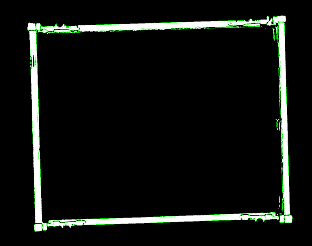
Output—Max outputs: Since the target object is a bin, set the Max outputs to 1.
-
After setting the above parameters, click the Run Step button. The matching result is shown in the figure below.
Configure Step Ports
After target object recognition, Step ports should be configured to provide vision results and point clouds for Mech-Viz for path planning and collision detection.
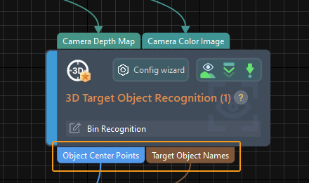
To obtain the position information of the real bin, select the Port(s) related to object center point option under Select port, and click the Save button. New output ports are added to the 3D Target Object Recognition Step, as shown below.
Adjust Poses (Target Object Poses)
After obtaining the target object poses, you need to use the Adjust Poses V2 Step to adjust the poses. Click the Config wizard button in the Step Parameters panel of the Adjust Poses V2 Step to open the pose adjustment tool for pose adjustment configuration. The overall configuration process is shown in the figure below.

-
To output the target object poses in the robot reference frame, please select the checkbox before Transform pose to robot reference frame to transform the poses from the camera frame to the robot frame.
-
Set Orientation to Point to reference point and Pointing axis to Z-axis, which enables the robot to pick target objects in the specified direction to avoid collisions.
-
Set the Sorting type to Sort by X/Y/Z value of pose, set Specified value of the pose to Z-coordinate, and sort the poses in Descending order.
-
To reduce the time required for subsequent path planning, target objects that cannot be easily picked need to be filtered based on the angle between the Z-axis of the pose and the reference direction. In this tutorial, you need to set the Max angle difference to 90°.
-
General settings.
Set number of new ports to 1, and a new input and output port will be added to the Step. Connect the input port to the Target Object Names output port of the 3D Target Object Recognition Step and connect the output port to the Output Step.
Adjust Poses (Bin Poses)
After obtaining the bin pose, you need to use the Adjust Poses V2 Step to adjust the pose. Click the Config wizard button in the Step Parameters panel of the Adjust Poses V2 Step to open the pose adjustment tool for pose adjustment configuration. The overall configuration process is shown in the figure below.

-
Select pose processing strategy.
Since the target object is a deep bin holding target objects, please select the Bin option.
-
To output the bin pose in the robot reference frame, please select the checkbox before Transform pose to robot reference frame to transform the pose from the camera frame to the robot frame.
-
Translate poses along specified direction.
In the Robot reference frame, move the bin pose along the Positive Z-direction and manually adjust the Translation distance to -285 mm to move the bin pose from the top surface of the bin down to the bin center, which will be used to update the bin collision model in Mech-Viz later.
Translation distance = -1 × 1/2 Bin height -
To reduce the time required for subsequent path planning, target objects that cannot be easily picked need to be filtered based on the angle between the Z-axis of the pose and the reference direction. In this tutorial, you need to set the Max angle difference to 90°.
-
General settings.
Set number of new ports to 1, and a new input and output port will be added to the Step. Connect the input port to the Target Object Names output port of the 3D Target Object Recognition Step and connect the output port to the Output Step.
Output Object Information
Use the Output Step to output the object center point, preprocessed point cloud, target object name, bin name, bin pose, etc., to Mech-Viz for path planning.
Path Planning
Once the target object recognition is complete, you can use Mech-Viz to plan a path and then write a robot program for picking the target objects.
The process of path planning configuration is shown in the figure below.

Configure Scene Objects
Scene objects are introduced to make the scene in the software closer to the real scenario, which facilitates the robot path planning. For detailed instructions, please refer to Configure Scene Objects.
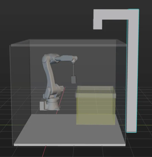
To ensure effective picking, scene objects should be configured to accurately represent the real operating environment. The scene objects in this solution are configured as shown below.
Configure Robot Tool
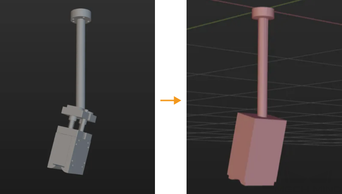
The end tool should be configured so that its model can be displayed in the 3D simulation area and used for collision detection. For detailed instructions, please refer to Configure Tool.
|
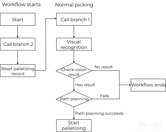
Adjust the Workflow
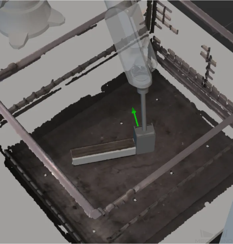
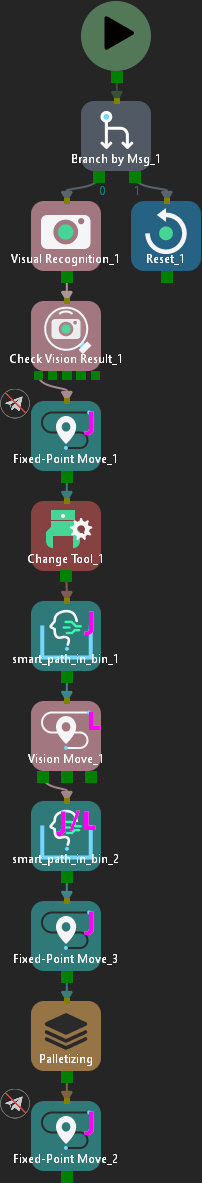
The workflow refers to the robot motion control program created in Mech-Viz in the form of a flowchart. After the scene objects and end tools are configured, you can adjust the project workflow according to the actual requirements. The flowchart of the logical processing when picking the target object is shown below.
Examples of the successful robot picking are shown below:
-
Pick on the front of the target object with the front of the tool:
-
Pick on the corner of the target object with the front of the tool:
-
Pick on the front of the target object with one side of the tool:
-
Pick on the side of the target object with one side of the tool:
When Standard Interface communication is used, the workflow of the project is shown below.
Simulate and Test
Click the Simulate button on the toolbar to test whether the vision system is set up successfully by simulating the Mech-Viz project.
Place the target object randomly in the bin and click Simulate in the Mech-Viz toolbar to simulate picking the target object. After each successful picking, the target object should be rearranged, and 10 simulation tests should be conducted. If the 10 simulations all lead to successful pickings, the vision system is successfully set up.
If an exception occurs during simulation, refer to the Solution Deployment FAQs to resolve the problem.
Robot Picking and Placing
Write a Robot Program
If the simulation result meets expectations, you can write a pick-and-place program for the ABB robot.
The example program Kawasaki example programs for picking can basically meet the requirements of this typical case. You can modify the example program. For a detailed explanation of the Kawasaki example programs for picking, please refer to Example Program Explanation.
Modification Instruction
Based on the example program, please modify the program files by following these steps:
-
Define the TCP.
Before modification After modification (example) TOOL gripper ;set TCP
  point tcp1 = trans(0,37.517,390.13,-15,0,0)
  TOOL tcp1 ;set TCP
-
Set the DO port to add tool control logic to initialize the tool status.
Before modification After modification (example) /
signal 10,-9;set do off
-
Specify the IP address and port number of the IPC. Change the IP address and port number in the MM_Init_Socket command to those in the vision system.
Before modification After modification (example) ;Set ip address of IPC call mm_init_skt(127,0,0,1,50000)
  ;Set ip address of IPC
  call mm_init_skt(128,1,1,2,60000)
-
Trigger the Mech-Viz project to run, switch to branch 2 to reset palletizing records, and then switch to branch 1 to start visual recognition. Then determine whether branch 2 needs to be used for visual recognition according to the status code indicating whether the planned path is successfully obtained fromMech-Viz.
Before modification After modification ;Run Viz project call mm_start_viz(1,#start_viz) ;(2,#start_viz) used for ETH viz initial position twait 0.1 ;set branch exitport ;call mm_set_branch(1,1) ;get planned path call mm_get_vizdata(2,pos_num,vispos_num,ret1)
  ;Init Palletizing
  CALL mm_start_viz(2,#start_viz);(2,#start_viz) used for ETH viz initial position
  TWAIT 0.1
  call mm_set_branch(7,2);init Palletizing
  TWAIT 0.1
  CALL mm_start_viz(2,#start_viz);(2,#start_viz) used for ETH viz initial position
  TWAIT 0.1
  call mm_set_branch(7,1)
 10 CALL mm_get_vizdata(1,pos_num,vispos_num,ret1)
-
Move the robot along the planned path to the pick point, and set the DO port to add a signal to close the gripper to pick the target object.
Before modification After modification (example) ;follow the planned path to pick for count =1 to pos_num speed speed[count] LMOVE movepoint[count] if count == vispos_num then ;add object grasping logic here;follow the planned path to pick JMOVE #movepoint[1] JMOVE #movepoint[2] JMOVE #movepoint[3] JMOVE #movepoint[4] LMOVE #movepoint[5] BREAK signal 9,-10;set do on TWAIT 0.2 LMOVE #movepoint[6] JMOVE #movepoint[7] JMOVE #movepoint[8]
-
Trigger the Mech-Viz project and switch to branch 1 to capture images in advance.
Before modification After modification /
CALL mm_start_viz(2,#start_viz);(2,#start_viz) used for ETH viz initial position TWAIT 0.1 call mm_set_branch(7,1)
-
Move the robot to the placing waypoint.
Before modification After modification /
;go to drop location JMOVE #movepoint[9] JMOVE #movepoint[10] break twait 0.2 JMOVE #movepoint[11] -
Set the DO port to perform placing. Note that the DO command should be set according to the actual DO port number used on site.
Before modification After modification (example) ;add object releasing logic here
signal 10,-9;set do on
-
Insert the loop statement for a pick-and-place cycle.
Before modification After modification (example) /
JMOVE #camera_capture;move to camera_capture position GOTO 10
Reference: Modified Example Program
.PROGRAM vision_sample_2()
;---------------------------------------------------------
;* FUNCTION:simple pick and place with Mech-Viz
;* mechmind
;---------------------------------------------------------
accuracy 1 always
speed 30 always
point tcp1 = trans(0,37.517,390.13,-15,0,0)
TOOL tcp1 ;set TCP
signal 10,-9;set do off
Home ;move robot home position
JMOVE camera_capture ;move to camera_capture position
break
pos_num = 0
;Set ip address of IPC
call mm_init_skt(128,1,1,2,60000)
twait 0.1
;Set vision recipe
;call mm_switch_model(1,1)
;Init Palletizing
CALL mm_start_viz(2,#start_viz);(2,#start_viz) used for ETH viz initial position
TWAIT 0.1
call mm_set_branch(7,2);init Palletizing
TWAIT 0.1
CALL mm_start_viz(2,#start_viz);(2,#start_viz) used for ETH viz initial position
TWAIT 0.1
call mm_set_branch(7,1)
10 CALL mm_get_vizdata(1,pos_num,vispos_num,ret1)
if ret1 <> 2100
halt
end
for count=1 to pos_num
call mm_get_pose(count,&movepoint[count],label[count],speed[count])
end
  ;follow the planned path to pick
  JMOVE #movepoint[1]
  JMOVE #movepoint[2]
  JMOVE #movepoint[3]
  JMOVE #movepoint[4]
  LMOVE #movepoint[5]
  BREAK
  signal 9,-10;set do on
  TWAIT 0.2
  LMOVE #movepoint[6]
  JMOVE #movepoint[7]
  JMOVE #movepoint[8]
  CALL mm_start_viz(2,#start_viz);(2,#start_viz) used for ETH viz initial position
  TWAIT 0.1
  call mm_set_branch(7,1)
;go to drop location
    JMOVE #movepoint[9]
    JMOVE #movepoint[10]
    break
    twait 0.2
    JMOVE #movepoint[11]
end
signal 10,-9;set do on
  JMOVE #camera_capture;move to camera_capture position
  GOTO 10
ENDPicking Test
To ensure stable production in the actual scenario, the modified example program should be run to perform a picking test with the robot. For detailed instructions, please refer to Test Standard Interface Communication.
Before performing the picking test, please teach the following waypoints.
| Name | Variable | Description |
|---|---|---|
Tool Center Point |
TCP |
Defined by the pose variable “gripper.” Please use the teach pendant to teach. |
Home position |
home |
The taught initial position. The initial position should be away from the objects to be picked and surrounding devices, and should not block the camera’s field of view. |
Image-capturing position |
camera_capture |
The taught image-capturing position. The image-capturing position refers to the position of the robot where the camera captures images. At this position, the robot arm should not block the camera’s FOV. |
Placing waypoint |
movepoint[11] |
The position for placing the target object. |
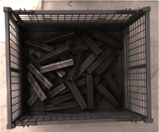
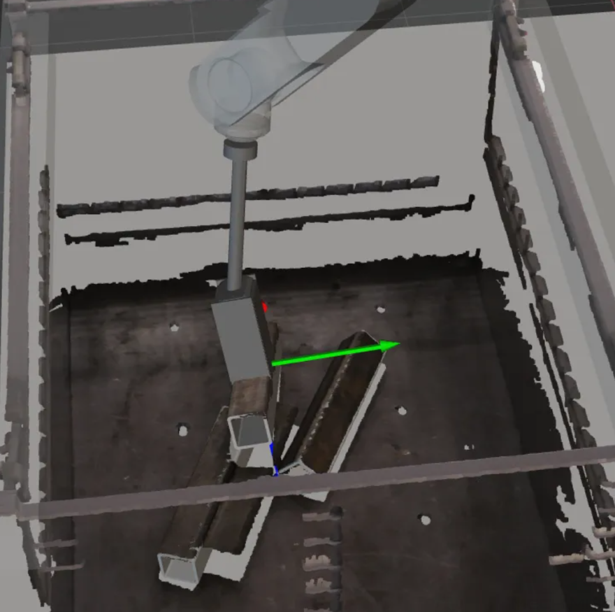
After teaching, arrange the target objects as shown in the table below, and use the robot to conduct picking tests for all arrangements at a low speed.
The picking tests can be divided into three phases:
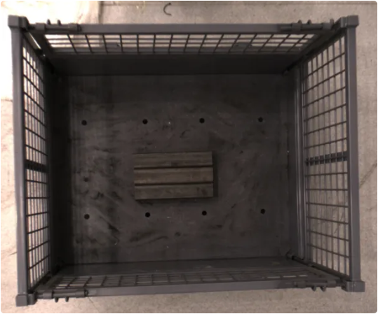
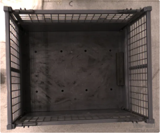
Phase 1: Test with Single Target Object
Object placement status |
Illustration |
Target object placed in the left-right direction in the middle of the bin |
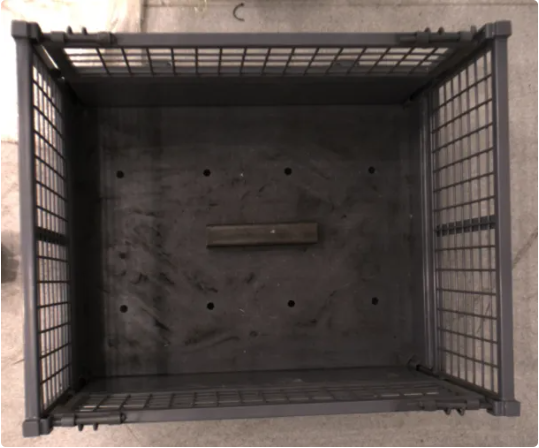
|
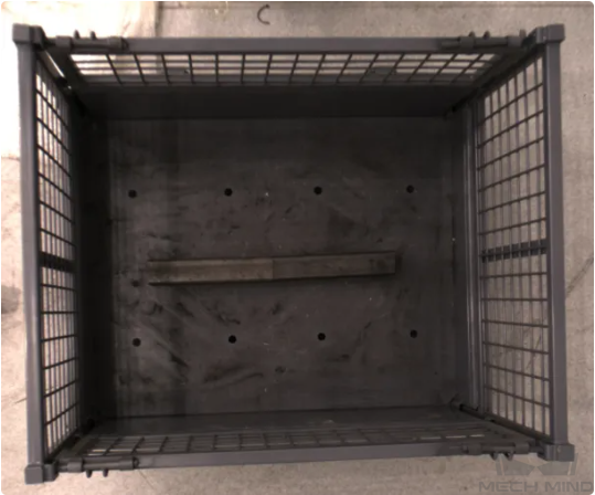
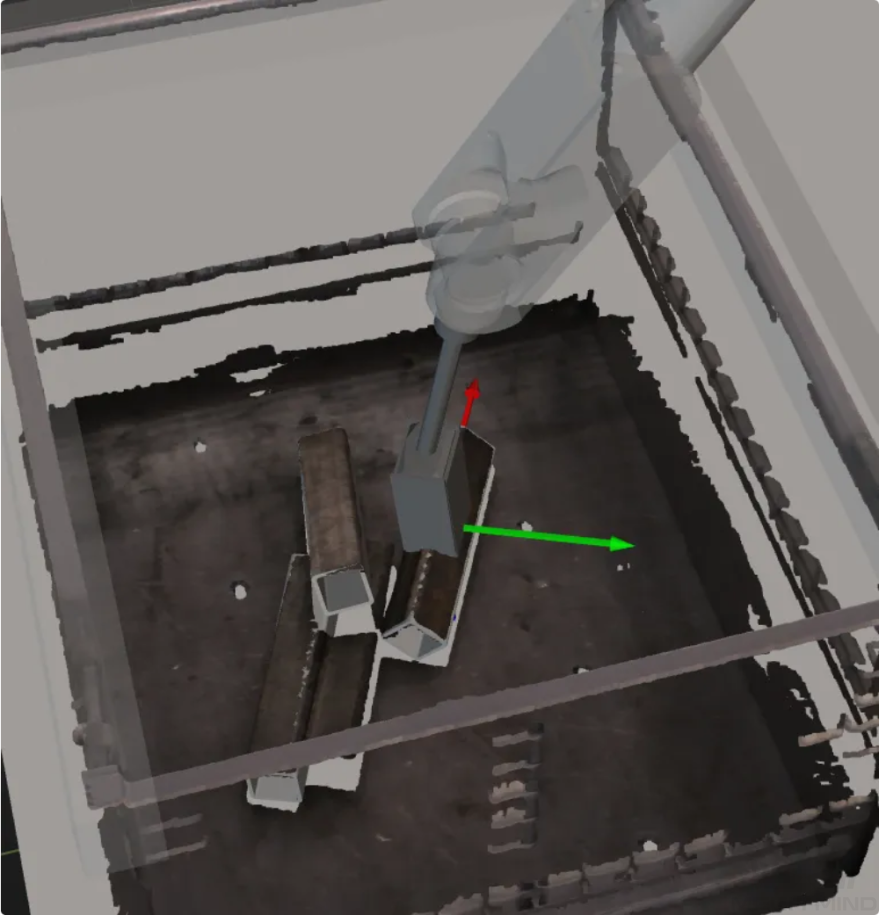
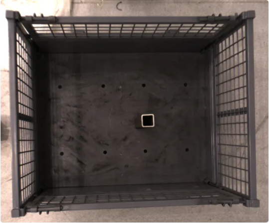
Target object placed in the top-down direction in the middle of the bin |

|
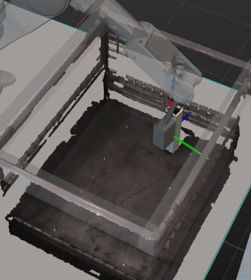
Target object placed vertically in the middle of the bin |
|
The target object is placed in the corner of the bin |
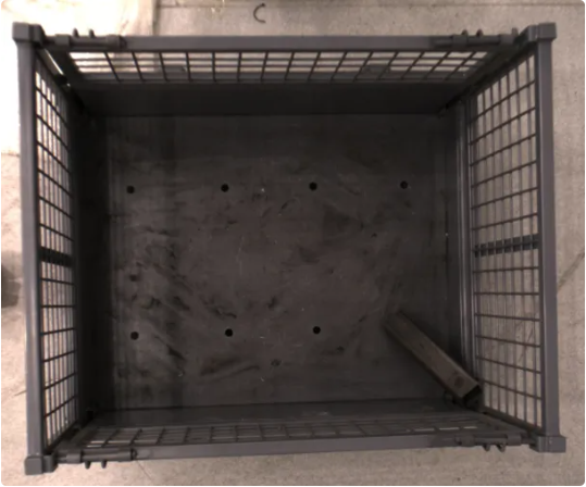
|