Solution Design
This section introduces the solution design of the Highly Reflective Discs solution, including the workflow of the vision system, software combination, camera model selection, and calibration board selection.
Software Combination
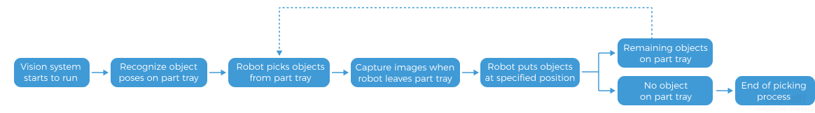
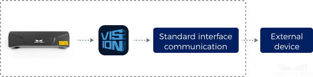
This solution uses Mech-Vision to recognize the poses of highly reflective discs and plan the path for picking them.
As shown below, Mech-Vision plans a robot picking path based on the poses and sends the planned path to an external device (such as a robot, PLC, etc.) through Standard Interface communication.
Select Camera and Determine Mounting Height
Considering the camera’s field of view, accuracy, and working distance, it is recommended to use Mech-Eye LSR L-GL industrial 3D camera (hereinafter referred to as LSR L-GL camera) for loading highly reflective discs. The camera has high accuracy, fast speed, and excellent resistance to ambient light. For detailed technical specifications of the camera, please refer to LSR L-GL Technical Specifications. If you need to use a camera of other models, please use the 3D Camera Selector to select the appropriate model.
After determining the camera model, please use the 3D Camera Selector to determine the mounting height of the camera. Follow the steps below:
-
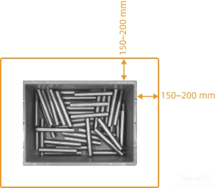
Determine the dimensions of the objects on the top layer and the possible maximum height, and fill in the Length, Width, and Height in the Object dimensions panel.
To accommodate deviations in the position of the incoming objects, a margin of 150–200 mm should be left on each side of the top layer, as shown below. Namely, the length and height values should equal the dimensions of the top layer of the objects plus the reserved margin shown in the figure below.
-
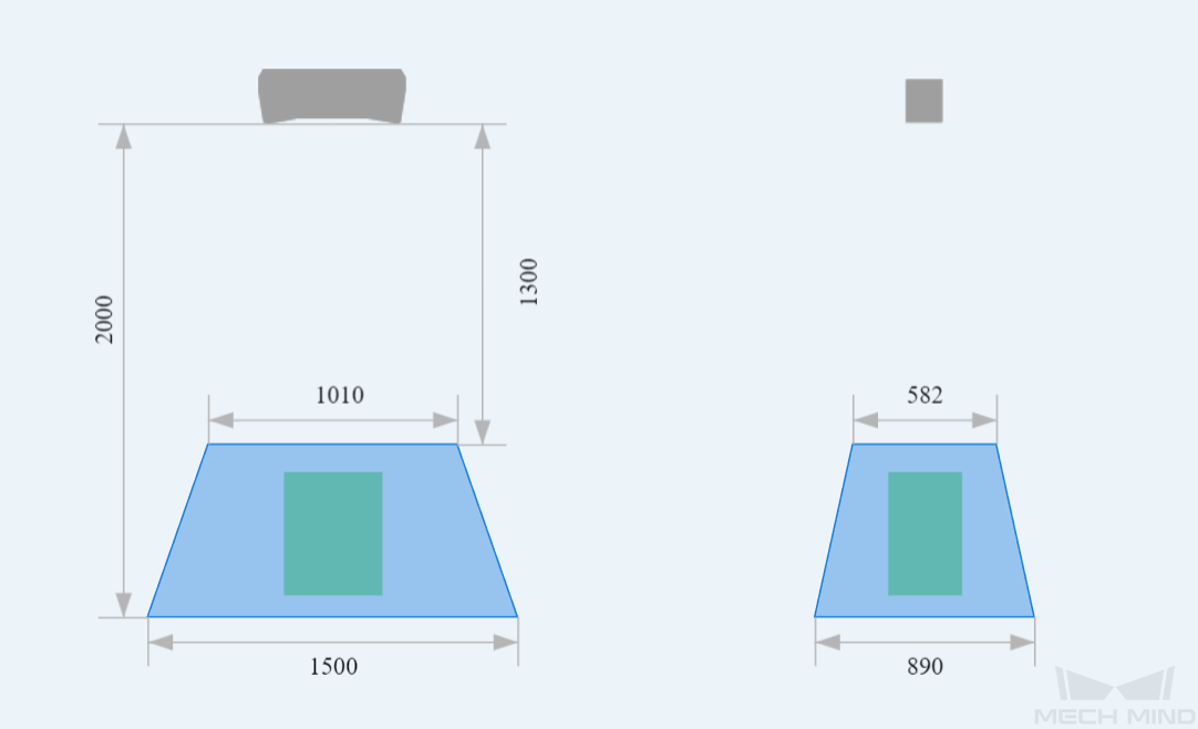
Turn on the switch to the right of Distance from camera to object and keep adjusting the parameter value until the square on the right that represents the object is at the center of the camera FOV and is completely covered, i.e., the square becomes green.
-
Mounting height = Distance from camera to object + object height
To ensure good data quality, the distance from the camera to the top layer of the object should be within the recommended working distance, provided that the requirements of the FOV and robot workspace are met.
Select IPC Model
The recommended IPC is Mech-Mind IPC STD, which is suitable for regular depalletizing and loading scenarios.
Select Robot Model
To pick highly reflective discs, a 6-axis robot with a large picking range and high accuracy should be selected according to the picking range and accuracy requirements. The ABB_IRB_6700_150_3_20 robot is used as an example in this solution.
For robots of other brands, please refer to Robot Model Selection.
Workstation Layout Design
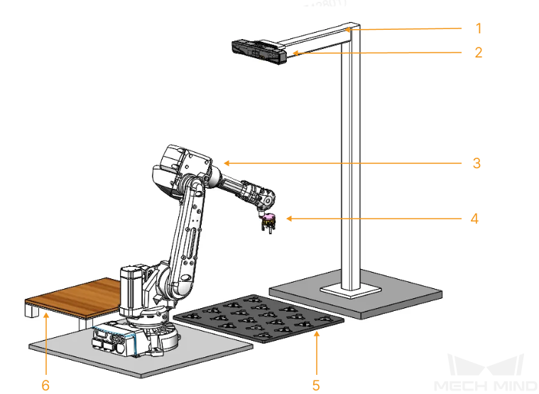
The layout of the on-site workstation is shown in the figure below. The LSR L-GL camera is mounted 2 meters directly above the part tray. After capturing images, the camera can acquire point clouds of all target objects. The parts in the figure are: 1-camera mounting frame; 2-LSR L-GL camera; 3-robot; 4-robot tool; 5-infeed tray; and 6-palletizing position.
Robot Tool Design
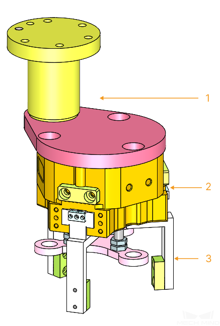
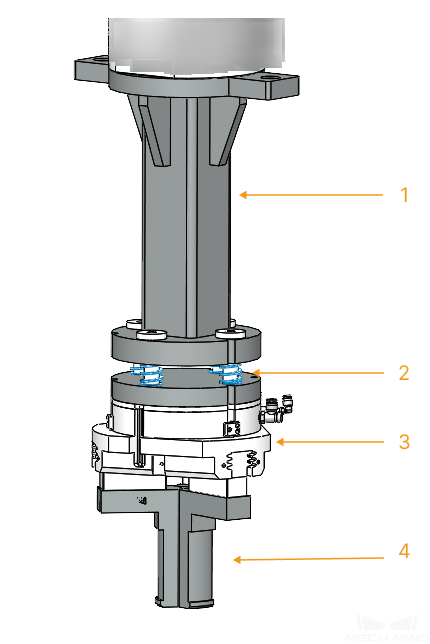
There are two types of common grippers used to pick highly reflective discs: three-finger external gripper and three-finger internal gripper. The usage scenarios and structures of the two types of grippers are shown in the table below:
| Type | Three-finger external gripper | Three-finger internal gripper |
|---|---|---|
Application scenario |
There are grooves around the target object on the part tray that allow the gripper to be inserted |
There are grooves or a through hole on the surface of the target object that allow the gripper to be inserted |
Illustration |
|
|
Structure |
1-Mounting flange; 2-Three-finger pneumatic cylinder; 3-Clamp gripper |
1-Mounting flange; 2-Spring block; 3-Three-finger pneumatic cylinder; 4-Expansion gripper |
|