3D Camera Model Selection and Mounting
This section will introduce the camera selection method and mounting modes during the hardware installation process.
Select Camera Model
In the actual application of single-case sack depalletizing, the Mech-Eye DEEP camera is usually selected.
Mech-Eye DEEP cameras feature large field of view, large depth of field, and excellent resistance to ambient light. For detailed technical specifications, please refer to DEEP Technical Specifications.
Camera Mounting Mode
There are two common camera mounting modes: Eye in Hand (EIH) and Eye to Hand (ETH), as shown in the left and right figures below respectively.
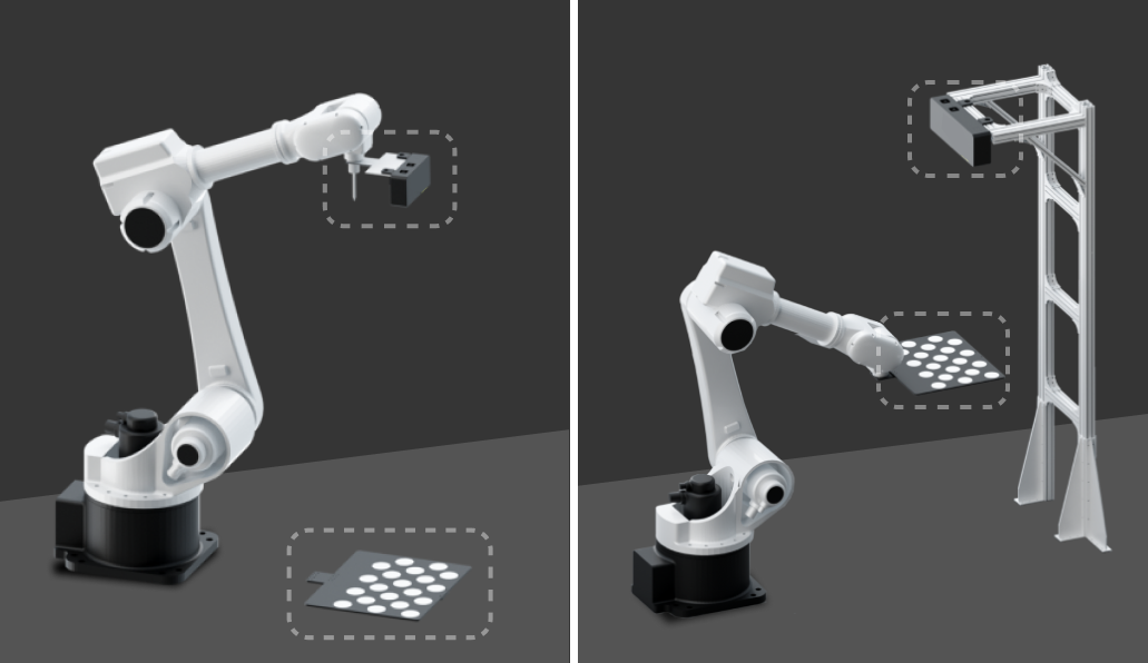
The characteristics and advantages of the two camera mounting modes are shown in the table below.
| Mounting mode | Characteristics | Advantages |
|---|---|---|
Eye in Hand |
The camera is mounted on the robot tool. |
|
Eye to Hand |
The camera is fixedly mounted on the camera stand. |
|
Camera Mounting Height
When determining the camera mounting height, you can use the Mech-Eye Industrial 3D Camera FOV Calculator , and obtain the full stack height of the sacks and the possible maximum height of the workstation in advance. Follow the steps below.
-
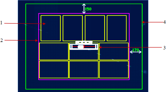
Calculate the camera’s field of view at the top of the stack.
The camera’s field of view should completely cover the upper surface of the top-layer sacks, and a margin of 150–200 mm should be left on each side of the field of view at the top of the bin to deal with the deviation of the incoming workpieces. As shown below, 1 is the sack, 2 is the pallet, 3 is the camera, and 4 is the camera’s field of view.
-
Use the Mech-Eye Industrial 3D Camera FOV Calculator to calculate the working distance.
In the Mech-Eye Industrial 3D Camera FOV Calculator, select a proper camera model, then continuously adjust the value of the “Enter working distance” parameter until the calculation result is greater than the previously calculated camera’s field of view at the top of the stack. For detailed instructions on how to use the FOV calculator, please refer to Industrial 3D Camera FOV Calculator.
-
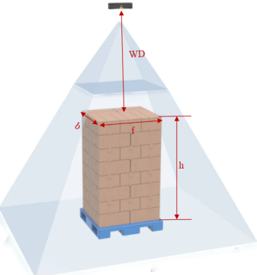
Calculate the camera mounting height.
As shown in the figure below, camera mounting height = working distance (WD) + stack height (H).
-
To ensure satisfactory data quality, make sure the distance between the camera and the upper surface of the top-layer sacks is within the range of the recommended working distance while meeting the requirements for the field of view and the robot’s motion space.
-
If the camera mounting height exceeds the selected camera’s maximum working distance, it is recommended to reduce the stack height of the incoming sacks or use a vertical camera mounting frame. Please refer to Camera Mounting Bracket Design for detailed instructions.
-