3D Camera Model Selection and Mounting
This section will introduce the camera selection method and mounting modes during the hardware installation process.
Select Camera Model
In actual applications of neatly arranged cylindrical shaft loading, the following three cameras are usually used.
-
Mech-Eye LSR L industrial 3D camera with high accuracy, large field of view, and high resistance to ambient light.
-
Mech-Eye PRO S industrial 3D camera with high accuracy, fast speed, high resistance to ambient light, and capability to function in medium-distance.
-
Mech-Eye PRO M industrial 3D camera with high accuracy, fast speed, high resistance to ambient light, and capability to function in medium-distance.
For detailed technical specifications of the above cameras, please refer to PRO S / PRO M Technical Specifications and LSR L Technical Specifications .
Camera Mounting Mode
Classification of Mounting Mode
There are two common camera mounting modes: Eye in Hand (EIH) and Eye to Hand (ETH), as shown in the left and right figures below respectively.
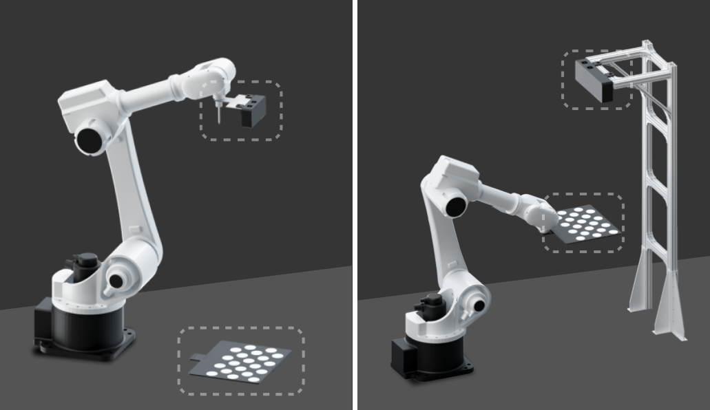
The characteristics and advantages of the two camera mounting modes are shown in the table below.
| Mounting mode | Characteristics | Advantages |
|---|---|---|
Eye in Hand |
The camera is mounted on the robot tool. |
|
Eye to Hand |
The camera is fixedly mounted on the camera stand. |
|
Precautions
For shaft picking projects, you need to pay attention to the following issues before mounting the camera.
-
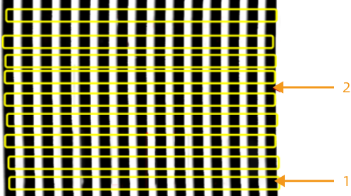
In order to improve the point cloud quality of the reflective shaft, when mounting the camera, the structured line from the laser profiler better be perpendicular to the axis of the shaft. As shown in the figure below, 1 is the axis shaft and 2 is the structured line.
-
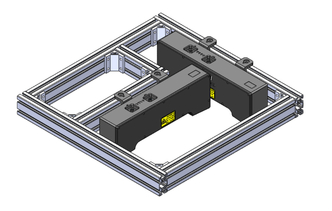
The infeed shafts can be placed in two positions: vertical and horizontal. In order to improve the point cloud quality of the shafts, two cameras can be mounted, as shown in the figure below.
Camera Mounting Height
When determining the camera mounting height, you can use the Mech-EyeIndustrial 3D Camera FOV Calculator , and obtain the height of the bin (or the possible extreme height of the workpiece) and the possible maximum height of the workstation in advance. Follow the steps below.
-
Calculate the camera’s field of view at the top of the stack.
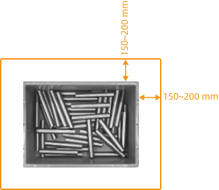
The camera’s field of view should completely cover the upper surface of the top-layer shafts, and a margin of 150–200 mm should be left on each side of the field of view at the top of the bin to deal with the deviation of the incoming workpieces, as shown in the figure below.
-
Use the Mech-Eye Industrial 3D Camera FOV Calculator to calculate the working distance.
In the Mech-Eye Industrial 3D Camera FOV Calculator, select a proper camera model, then continuously adjust the value of the “Enter working distance” parameter until the calculation result is greater than the previously calculated camera’s field of view at the top of the bin. For detailed instructions on how to use the FOV calculator, please refer toIndustrial 3D Camera FOV Calculator.
-
Calculate the camera mounting height.
As shown in the figure below, camera mounting height = working distance (WD) + stack height (H).
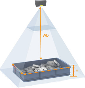
To ensure that the point cloud collected by the camera is of good quality, the camera mounting height should be less than the maximum working distance of the selected camera.