Basics
This section introduces the basics of the neatly arranged cylindrical shaft loading solution, including the applicability, unsupported functions and technical specifications.
Applicability
This section describes the applicability of the neatly arranged cylindrical shaft loading solution in terms of the condition of the incoming shafts, shaft types, project requirements, and the shaft placement.
Condition of Incoming Workpieces
| Feasible | Illustration | Not feasible | Illustration |
|---|---|---|---|
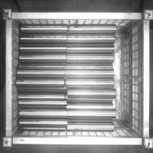
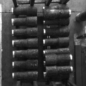
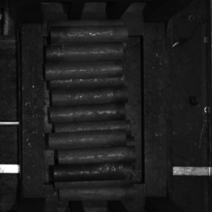
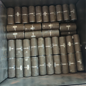
The shafts are placed in an orderly manner. |
|
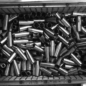
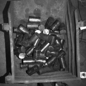
The shafts are placed in a random manner. |
|
Only one type of shaft exists in the same bin. |
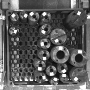
Various types of shafts exist in the same bin. |
Shaft Types
The table below illustrates the solution’s applicability to shaft types.
| Feasible | Illustration | Not feasible | Illustration |
|---|---|---|---|
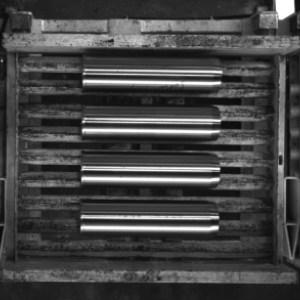
The shafts are standard cylinders. |
|
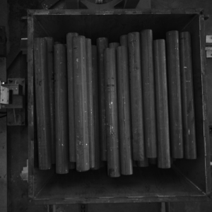
The workpieces are not standard cylinders. For example, the shaft is thinner at both ends and thicker in the middle or thicker at one end and thinner at the other. |
|
There is no need to differentiate the thin end and thick end of the shafts, as the shafts are standard cylinders with no significant differences between the two ends. |
|
It is needed to differentiate the big-endian and little-endian of the shafts, as there are significant differences between the two ends of the shafts. |
|
There are no significant grooves or grinding traces in the middle of the shafts. |
|
There are significant grooves or grinding traces in the middle of the shafts. |
|
Project Requirements
The table below illustrates the neatly arranged cylindrical shaft loading solution’s applicability to project requirements.
| Feasible | Illustration | Not feasible | Illustration |
|---|---|---|---|
Loading of shafts. Pick the shafts from the bins, and then place them on the loading platform or secondary positioning platform. |
|
Shaft unloading or assembly. |
|
There is no need to distinguish between the two ends of the shaft. |
It is necessary to distinguish the two ends of the shaft. |
Shaft Placement
The table below illustrates the solution’s applicability to shaft placement.
| Feasible | Illustration | Not feasible | Illustration |
|---|---|---|---|
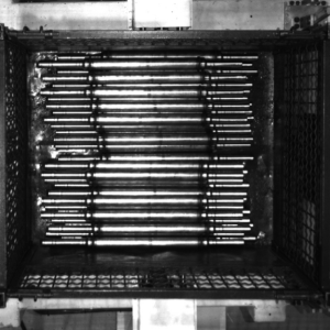
The shafts are placed in an orderly manner. The long sides of the shafts are parallel to the long side of the camera. |
|
The shafts are placed in a random manner. |
|
The shafts are placed in a left-right manner. |
|
The shafts are placed in a north-south manner. |
|
Shaft Carriers
The table below illustrates the solution’s applicability to shaft carriers.
| Feasible | Illustration | Not feasible | Illustration |
|---|---|---|---|
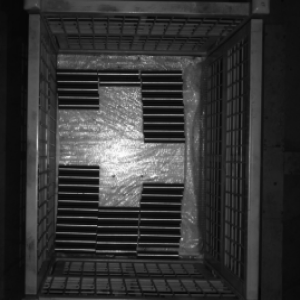
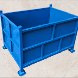
Four-wall bins with no significant reflection on the bin walls. There is no plastic film that obscures the shafts. |
|
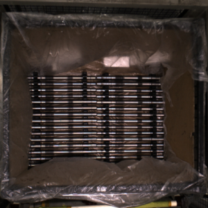
There is significant reflection on the bin walls, or there is plastic film obscuring the shafts. |
|
Dimensions
The table below illustrates the solution’s applicability to shaft dimensions.
| Feasible | Not feasible |
|---|---|
Shafts of known dimensions. |
Shafts of unknown dimensions. |
Collision Detection
The table below illustrates the solution’s applicability to collision detections.
| Feasible | Not feasible |
|---|---|
|
Detect collisions between objects of irregular shape. For example, detect collisions between the dresspack and the tool whose shape may change during the robot movement. |
Unsupported Functions
The neatly arranged cylindrical shaft loading solution does not support the following functions.
-
Identify the orientations of the shafts. The neatly arranged cylindrical shaft loading solution does not support the recognition of shafts with different ends, or the orientations of the shafts.
-
Identify different materials in the incoming shafts. The neatly arranged cylindrical shaft loading solution cannot be used to identify whether there are other types of materials in the incoming shafts.
-
Identify the dimensions of the shafts. The neatly arranged cylindrical shaft loading solution does not support the recognition of dimensions of the shafts.
Technical Specifications
The technical specifications of the neatly arranged cylindrical shafts loading solution are as follows.
-
Positioning accuracy: ±5 mm
-
Recognition success rate: more than 99%
-
Execution time of vision system: within 4 s
