Gripper Design
This section introduces the gripper design in turnover box depalletizing solution, including gripper design considerations and gripper design cases in various picking scenarios.
Principles of Design
This part describes the considerations in the gripper design process, as detailed below.
-
When designing the gripper, it is essential to fully consider the potential damage that the cylinder may cause to the side walls of the turnover box during clamping. Therefore, it is recommended to add a pressure reducing valve in the pneumatic circuit to reduce the clamping force.
-
It is necessary to ensure sufficient gripping margin, and generally, the single-side gripping margin should be greater than 3 mm. Since the turnover box may have certain deformation, a single-side margin greater than 6 mm is recommended.
-
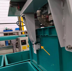
To accurately determine whether the gripper fingers have reached the correct position, photoelectric sensors can be added at the gripper finger locations. This device can detect the status of the fingers in real time. Once an abnormal condition is detected, the sensor will immediately trigger an alarm and prompt manual intervention, thereby effectively avoiding the risk of turnover box drop due to loose gripping and ensuring the safety and stability of the operation.
-
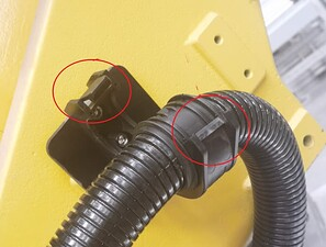
During the depalletizing process, the dresspack may experience significant swinging or large-angle bending. Therefore, metal-reinforced dresspacks or those with threaded hinge-type mounting brackets should be selected as much as possible. This design consideration applies to lateral gripping grippers and multi-grippers, etc.
Design Examples
This section will introduce the design cases of grippers used in some scenarios, and the details are as follows.
Loose Pallet Pattern
| Gripper example | Application scenarios | Gripper illustration | Figure legends |
|---|---|---|---|
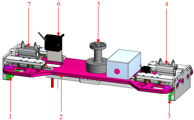
Top Picking Type |
Pallet pattern with loose arrangement along the long side direction of turnover boxes. |
|
1 Left clamp plate
|
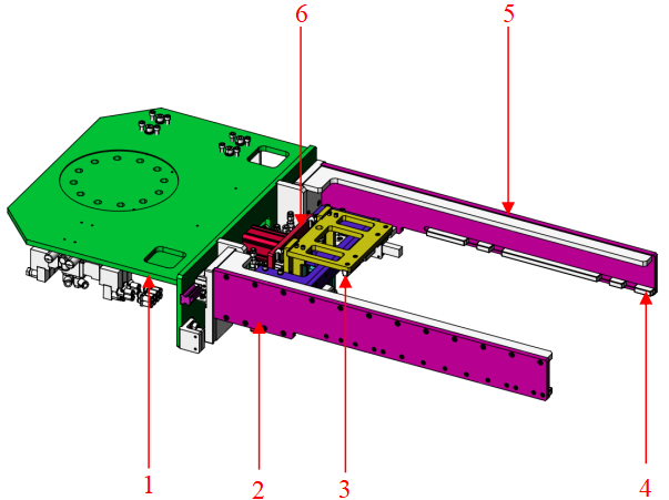
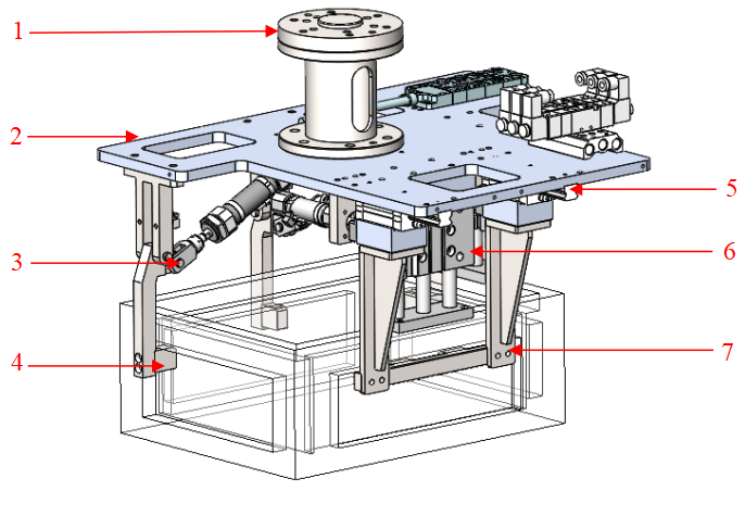
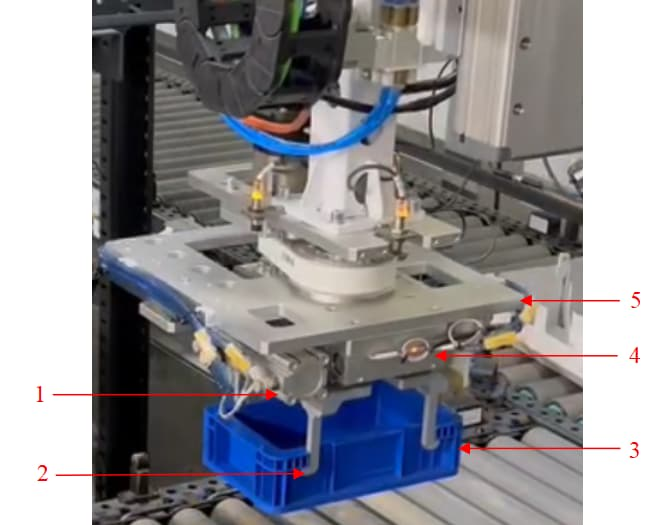
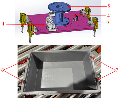
Side Picking Type |
Limited headspace at pick point and placing point; turnover box requires inversion or flipping after gripping. |
|
1 Flange mounting plate
|
Tight Pallet Pattern
| Gripper example | Application scenarios | Gripper illustration | Figure legends |
|---|---|---|---|
Long-side External Pulling Type |
Ample headspace at pick point and placing point; latches between adjacent layers of turnover boxes are loose; and the side walls of turnover boxes have areas with good strength and rigidity. |
|
1 Movable jaw base
|
Adjacent-side Clamping Type |
Uniform load distribution inside turnover box. If more weight is placed away from the pick point, there is a risk of turnover box tipping. |
|
1 Flange mounting plate
|
Picking Special Structures of Turnover Box
| Turnover box structure | Application scenarios | Gripper illustration | Figure legends |
|---|---|---|---|
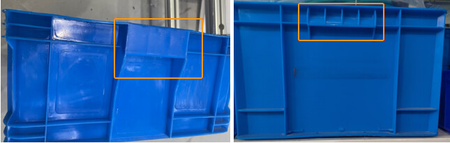
External Features on Side Walls |
The turnover box has external protrusions or internal recesses on its sidewalls. After the entire stack arrives, the gripper fingers can pick the boxes smoothly. |
|
1 Cylinder
|
Internal Features on Side Walls |
Turnover box side walls have external protrusions or internal recesses; internal contents do not interfere with picking. |
|
1 Directional valve
|
Picking Multiple Turnover Boxes
| Gripper example | Application scenarios | Gripper illustration | Figure legends | Precautions |
|---|---|---|---|---|
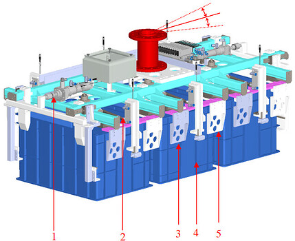
Top Multi-Pick Type |
High cycle time requirement; loose pallet pattern; standardized incoming turnover box arrangement; ample space at placing point. |
|
1 Longitudinal cylinder
|
When picking multiple turnover boxes simultaneously, ensure the gripper allows ±0.5° tolerance along the long-side picking direction to prevent scraping between gripper fingers and turnover boxes under extreme conditions. |
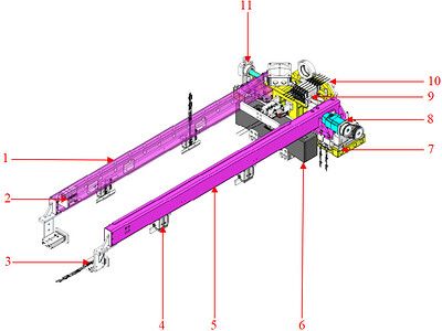
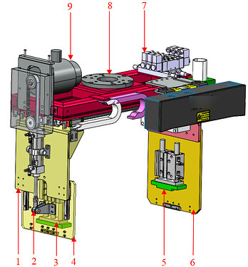
Side Multi-Pick Type |
High cycle time requirement; sufficient picking space on stack side; relatively standardized box placement; turnover boxes can be inverted after picking; ample space at placing point. |
|
1 Left bracket
|