Master-Control Communication Setup (KUKA KSS 9.x)
This guide shows you how to set up master-control communication with a KUKA robot (KSS 9.x).
Preparation
Check Controller and Software Compatibility
|
The models and versions listed below are tested and can be used. For other models and versions, you may refer to this guide for operation. If any issues occur, please contact Mech-Mind Technical Support. |
-
Controller model: KR C4 or KR C5
-
Controller system version: KSS 9.2 or above
Click here for instructions
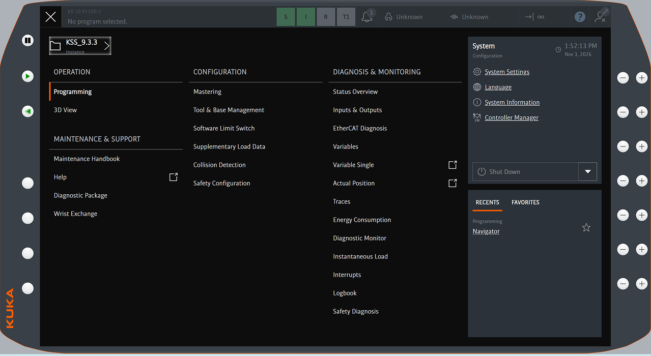
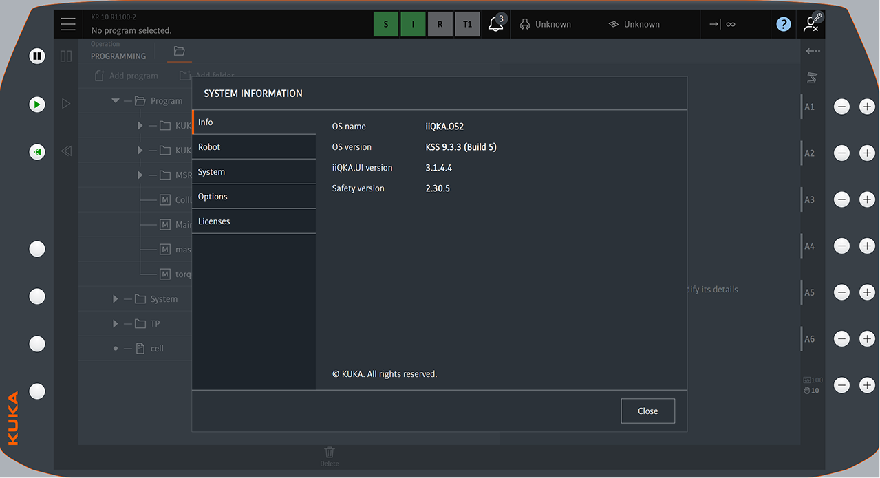
On the teach pendant, select to view the system version.
-
Add-on software package: Ethernet KRL (V6.1.2.12 or above)
Click here for instructions
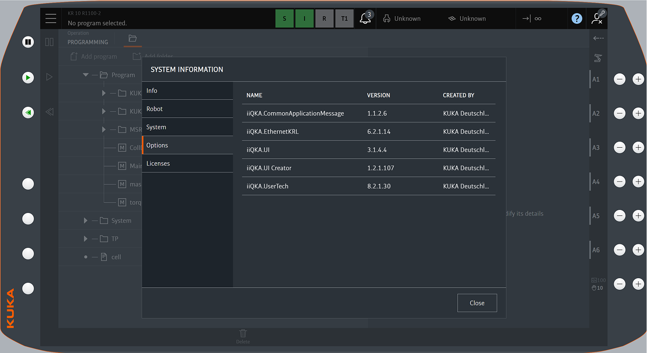
On the teach pendant, select to view the version information of Ethernet KRL.
-
Offline programming and simulation software (iiQWorks.Sim): iiQWorks.Sim 1.2 or above needs to be installed on the IPC or computer used for loading the program files.
Set up the Network Connection
Connect the Hardware
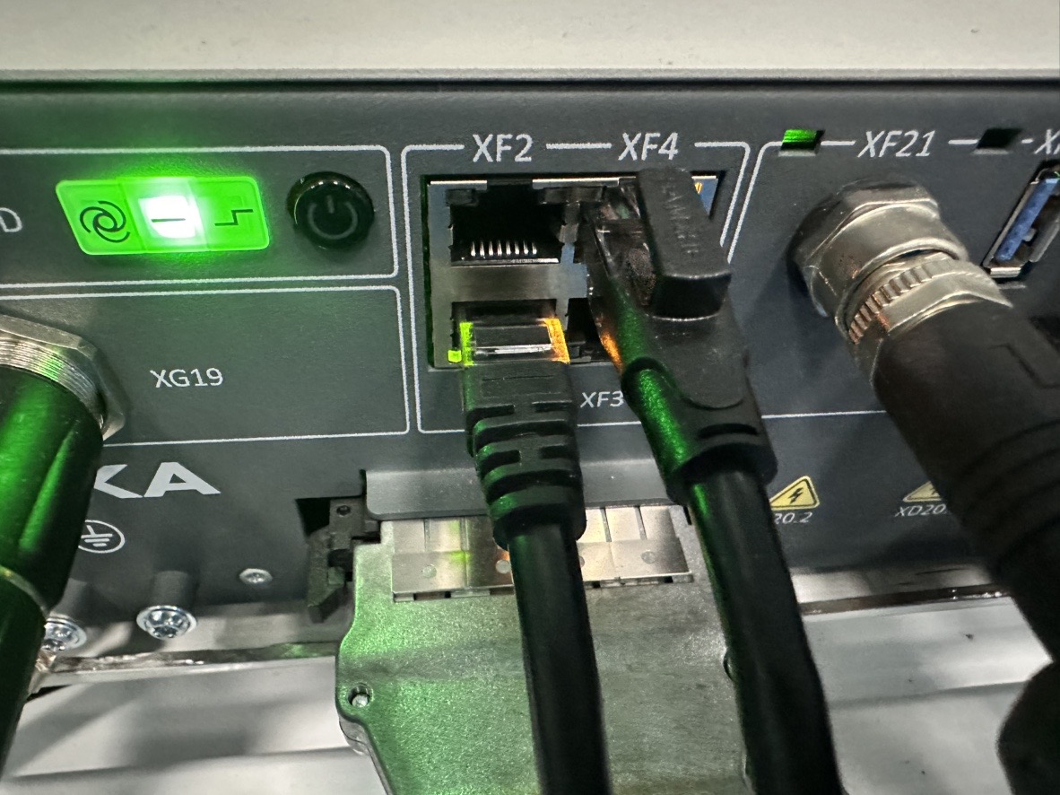
Plug one end of the network cable into the network port of the IPC, and plug the other end into port XF4 of the robot controller.
Switch to the Administrator User Group
-
Tap the User/SPOC display.
-
Select the “Administrator” user group.
-
Enter the password (the default password is “kuka”), and then click Login to confirm.
Set the IP Address
-
On the teach pendant, select to open the System Settings interface.
-
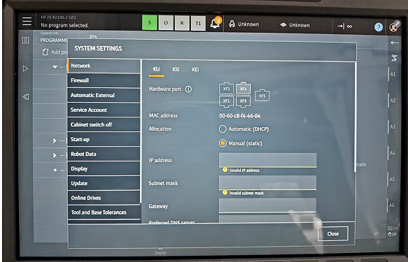
Select , confirm that the hardware port XF4 is connected, set Allocation to Manual (static), and then specify the IP address and Subnet mask.
-
In the IPC, set the IP address of the IPC.
The IP address of the IPC must be in the same subnet as that of the robot. That is, the network portions and subnet masks of both IP addresses must be the same. For example, 192.168.100.169/255.255.255.0 and 192.168.100.170/255.255.255.0 are in the same subnet.
Connect the Robot via iiQWorks.Sim
-
Open the iiQWorks.Sim software on the IPC.
-
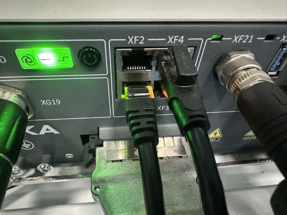
Plug one end of the network cable into the network port of the IPC, and plug the other end into port XF1 of the robot controller. The IPC will automatically obtain the network port information.
-
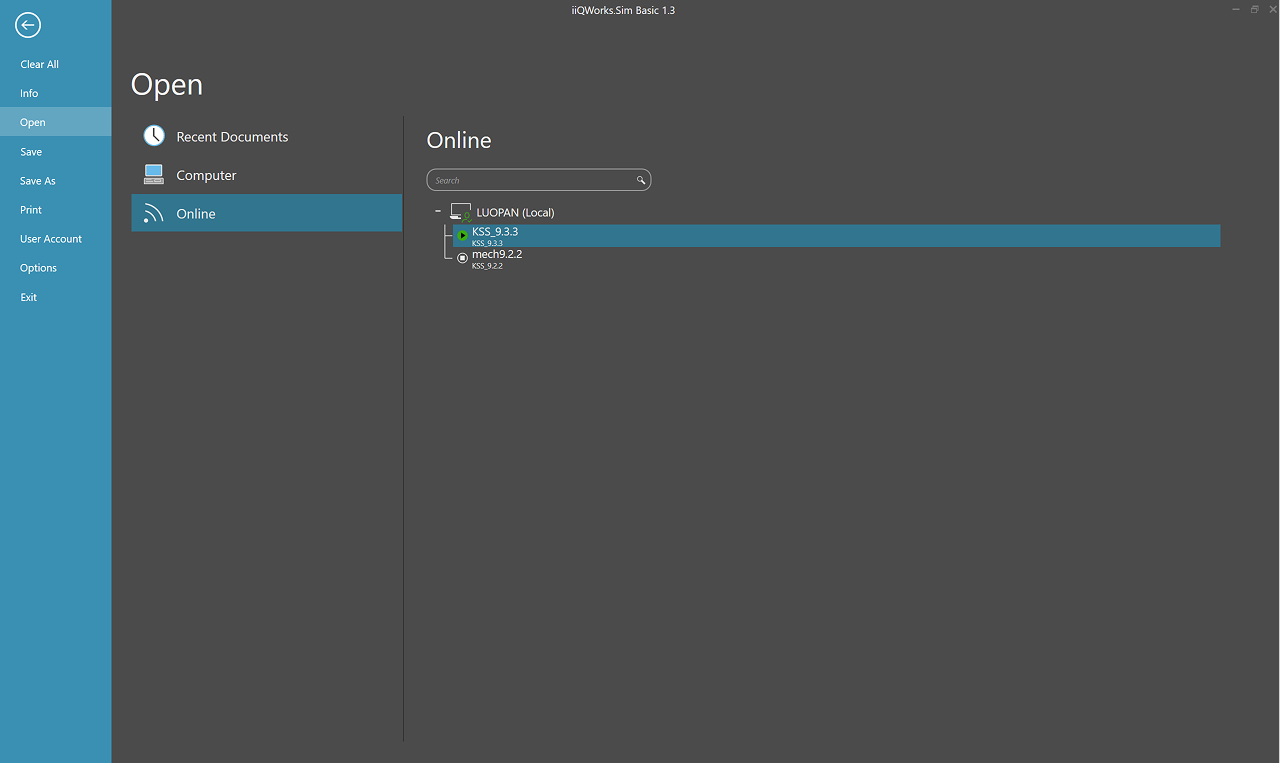
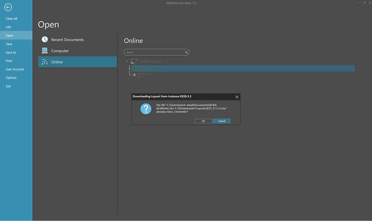
Select to view the online robots.
-
Double-click the robot to be connected. In the dialog box that appears, click OK to complete the connection.
Prepare Program Files
On the IPC, you can find the program folder in the Communication Component/Robot_Server/Robot_FullControl/kuka/kuka_v9 path in the installation directory of Mech-Vision and Mech-Viz.
If you use another computer to load the program files, copy the program folder from the IPC to that computer first.
Load the Program Files to the Robot
-
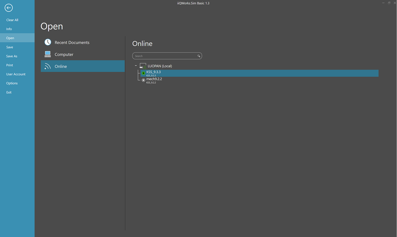
In the iiQWorks.Sim software, select , and then select the corresponding robot controller.
-
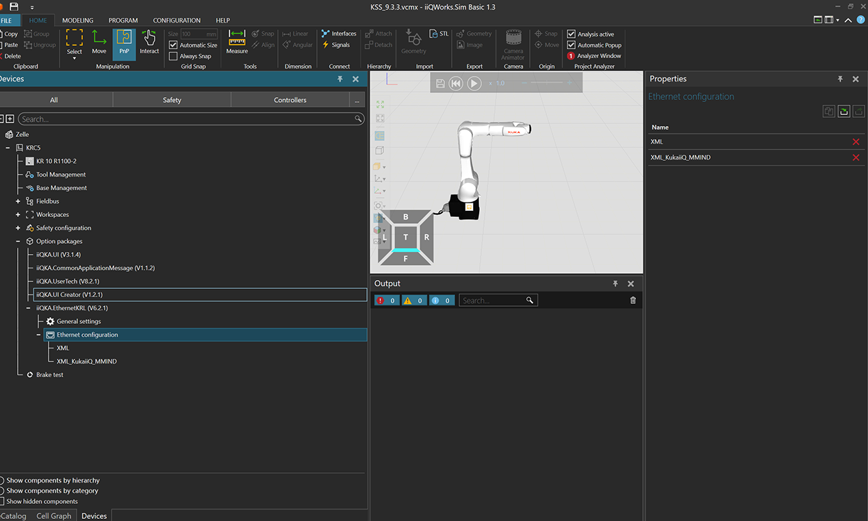
In the device list, select , and then click the Load button in the Properties panel on the right.
-
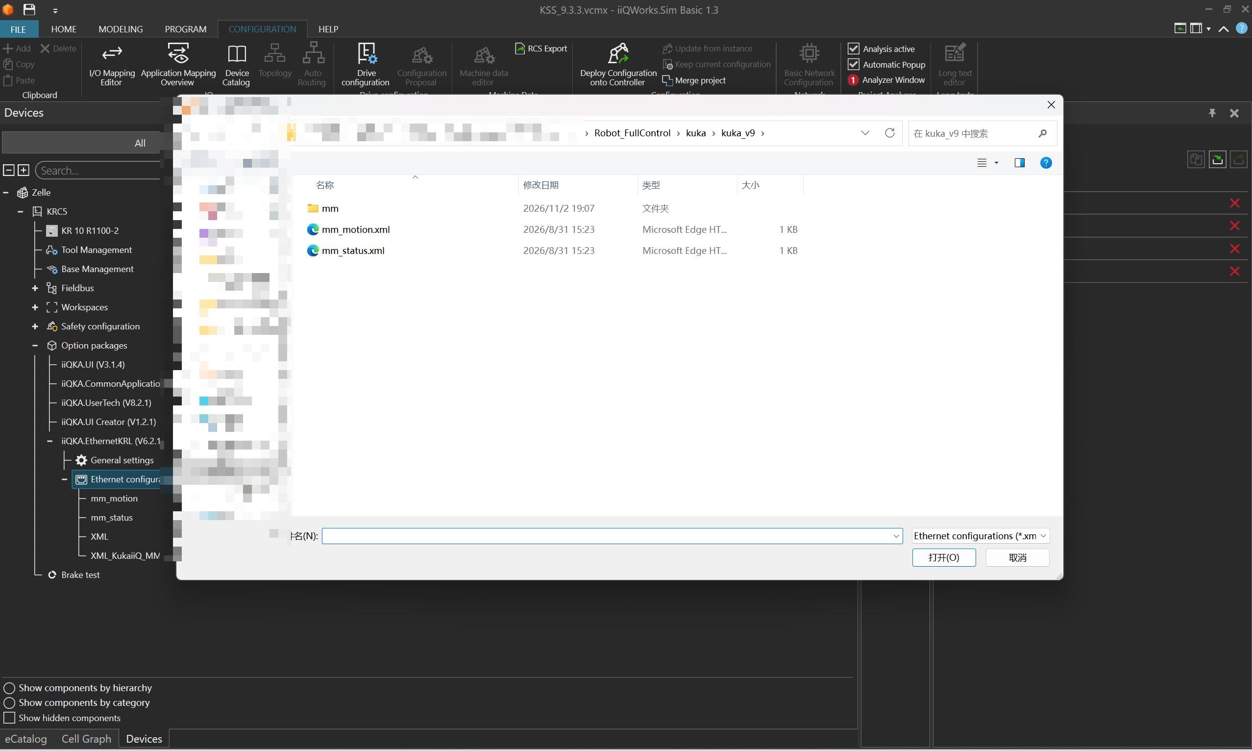
In the dialog box that appears, select the mm_motion.xml and mm_status.xml files (in the
Communication Component/Robot_Server/Robot_FullControl/kuka/kuka_v9/path in the software installation directory), and then click Open. -
In the
Communication Component/Robot_Server/Robot_FullControl/kuka/kuka_v9/path in the software installation directory, find the “mm” folder and copy the folder with Ctrl + C. -
On the menu bar, click the Program menu, and the robot program interface will be displayed. Select Program and paste the “mm” folder to the Program directory.
-
On the menu bar, select .
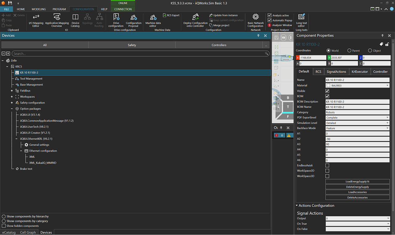
-
In the iiQWorks.Sim Project Deployment dialog box that appears, click Finish.
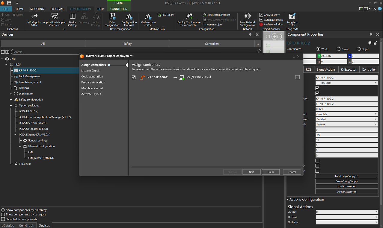
Test Master-Control Communication
-
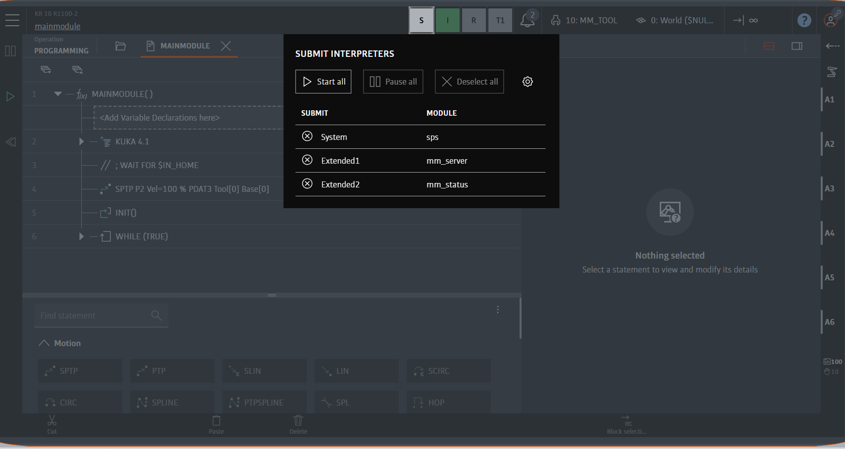
After switching the user to the Administrator user group, click the S button in the center of the screen, and then click the settings button on the right.
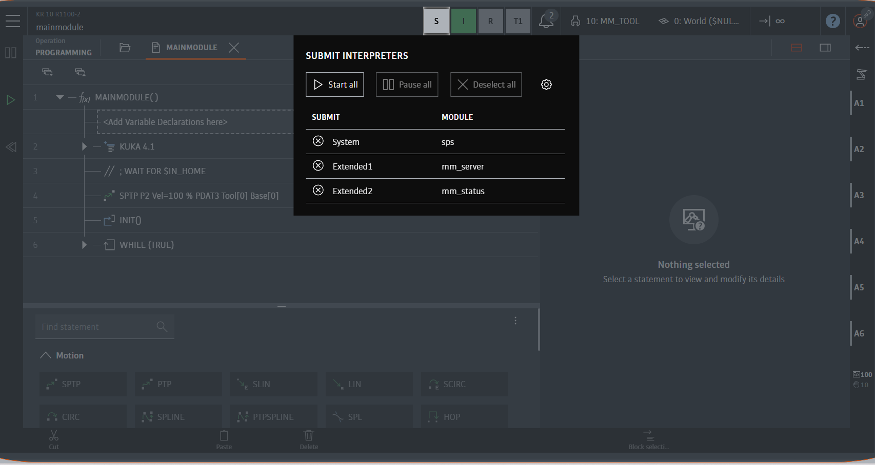
-
In the configuration interface, set Extended1 to mm_server and Extended2 to mm_status, and then click Close to save the settings.
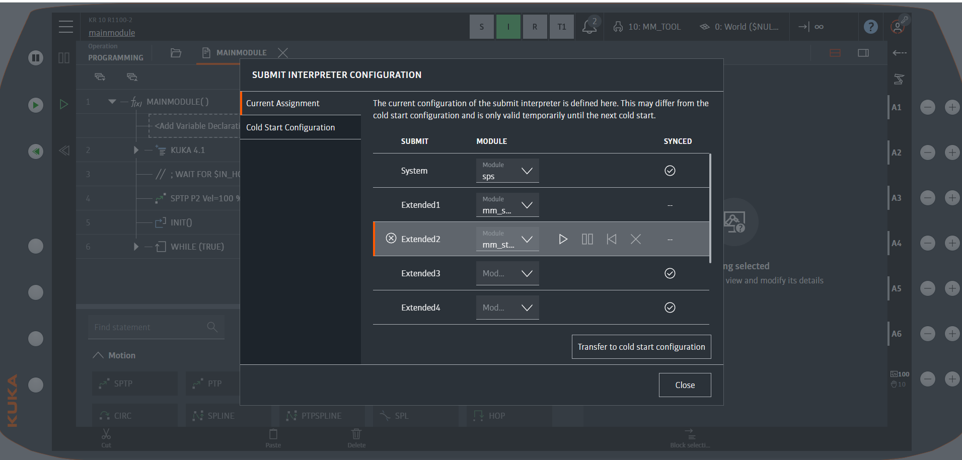
-
Click Start all, and wait for the background threads to start.
-
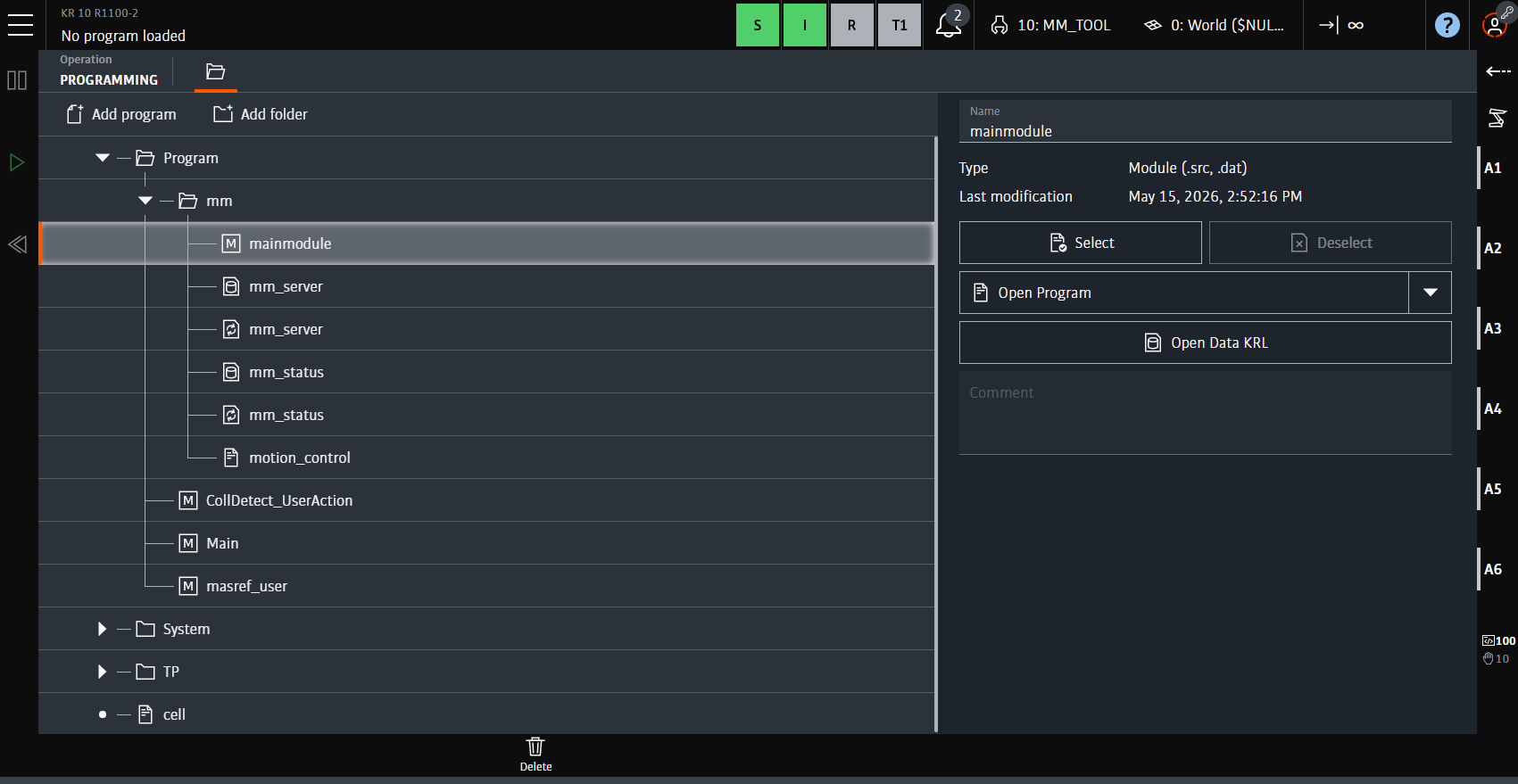
Select the mainmodule program under Program/mm, and then click Open Program on the right.
-
Move the robot manually to the HOME position.
-
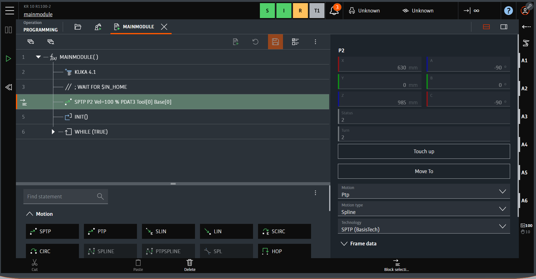
Click the “SPTP P2 Vel=100 % PDAT3 Tool[0] Base[0]” line to move the cursor to this line. Click Block selection, and a pointer appears in front of the line. Then, click Touch up.
-
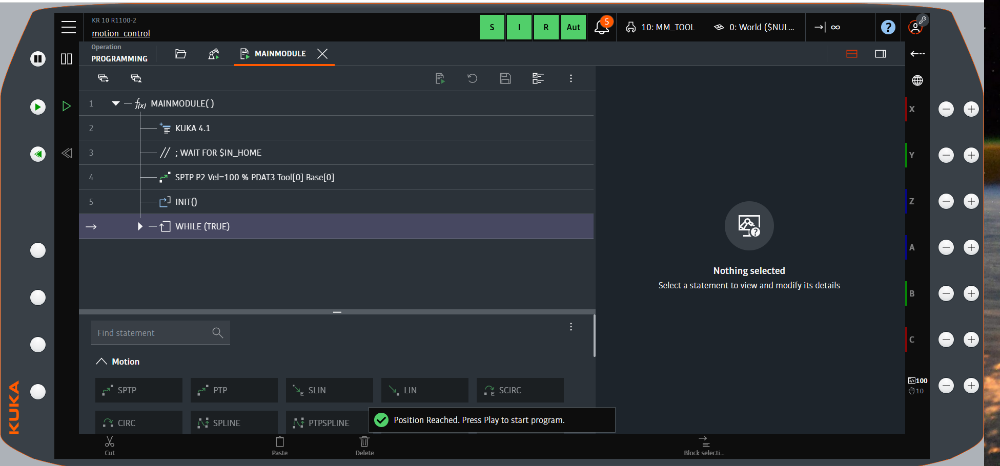
Click the save button at the top, close the program, and then switch to the Aut automatic mode for running.
-
Select the mainmodule program again, and then press the green play button on the side of the teach pendant.
Create a Mech-Viz Project
-
Open Mech-Viz, press Ctrl + N on the keyboard to create a new project. Select the robot model corresponding to your real robot brand and model on the interface as shown below.
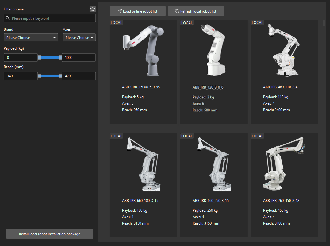
-
Press Ctrl + S and create or select a folder to save the project.
-
Right-click the project name in the left panel in Mech-Viz and select Autoload Project.
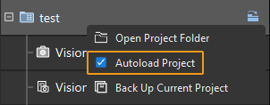
Connect to the Robot
-
Click Master-Control Robot on the toolbar of Mech-Viz.
-
Input the IP address of the real robot in Robot IP address (the IP address in the picture is only an example). Click Connect the robot.
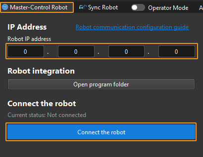
If Mech-Viz successfully connects the real robot, the current status will change to Connected. Meanwhile, the icon in the toolbar will turn from blue to green.
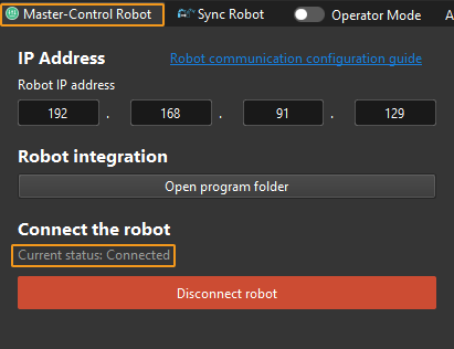
If the connection fails, please double-check the robot IP address.
Move the Robot
-
In the toolbar of Mech-Viz, change the “Vel.” (velocity) and “Acc.” (acceleration) parameters to 5%.

-
Click Sync Robot in the toolbar, and you can synchronize the poses of the simulated robot in the 3D simulation space with the poses of the real robot. Then click Sync Robot again to unselect it.

-
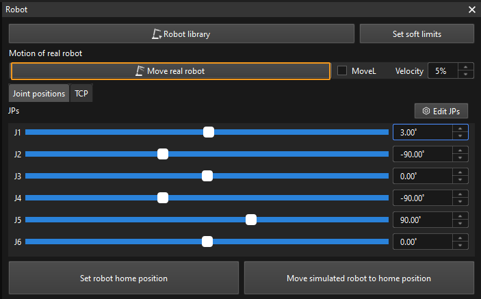
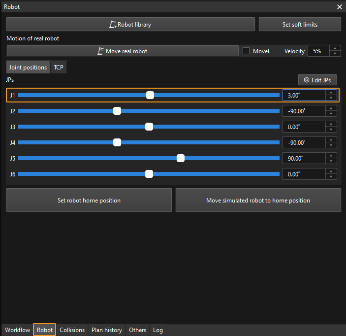
In the Robot tab, slightly adjust the value of “J1”, for example, from 0˚ to 3˚. This operation will move the simulated robot.
-
Click Move real robot and check if the real robot has moved. If the real robot has reached the JPs set for the simulated robot, the master-control communication is working.
When moving the robot, please ensure the safety of personnel. In the case of an emergency, press the emergency stop button on the teach pendant!