LSR L
Safety Instructions
-
To ensure safe use, please do not use the product before reading this manual and becoming familiar with the correct usage. Improper use and maintenance may damage the product or cause other hazards. Mech-Mind shall not be liable for any injury or damage brought upon the user or any third party due to improper use and maintenance.
-
Following the instructions and warnings in this manual can lower risks, but can not totally eliminate all risks.
-
Every step has been inspected during the drafting of this user manual. Please do not hesitate to contact Mech-Mind if you find any problems or mistakes in the manual.
-
This product is to be mounted, connected, used and maintained by trained adults only. To ensure safe operation, the product should be transported, stored, mounted, connected, used and maintained properly.
-
Laser is hazardous; please familiarize yourself with hazard prevention before using the camera.
 Precautions for Mounting and Using the Camera
-
It is PROHIBITED to place any explosive or flammable substances near the camera. Do not expose the camera to open fire or high temperature.
-
Do not throw, drop, or collide the camera with other objects. The camera may be damaged by strong shock or vibration. It is PROHIBITED to modify the camera in any form. Do not repair or disassemble the camera by yourself. Mech-Mind shall not be liable for any damage caused by repair or disassembly not performed by Mech-Mind.
-
Do not allow any foreign object, such as metal pieces, dust, paper, and wood chips, to enter the camera. Failure to do so may lead to fire, electric shock, malfunction, etc.
-
Do not use the camera at extremely high or low temperature. The operating temperature range is -10–45°C for the LSR and DEEP series, and 0–45°C for other series.
-
Please use the camera indoors.
-
Please use the camera at elevations below 4,000 meters.
-
Please install the camera in a well-circulated, open place.
Check the Camera
-
Before using, please check the camera carefully for damage, signs of water entry, suspicious odor, smoke, loose or damaged bolts, etc., and make sure that the camera is in proper working conditions. If any of the above abnormalities occur, please disconnect the power immediately.
-
High temperature will age the power cable. Please check the power cable regularly for signs of aging. If the cable has aged, please contact Mech-Mind to acquire a replacement.
Usage of Adapter/DIN Rail Power Supply
-
DO NOT use if the power port, adapter/DIN rail power supply, or power socket is wet.
-
DO NOT heat or put the adapter/DIN rail power supply and power cable in fire.
-
For power, please use a 24 V isolated adapter with an output power of at least 90 W or a 24 V isolated DIN rail power supply.
-
Please use the specified voltage. Failure to do so may lead to fire, electric shock, malfunction, etc. The adapter/DIN rail power supply and power cable should be properly grounded. It is recommended to use the isolated adapter/DIN rail power supply provided by Mech-Mind.
-
Power plugs should be properly grounded. Do not place the adapter/DIN rail power supply in a place that is hard to disconnect the power.
-
Please install the DIN rail power supply inside a control cabinet.
Precautions for Using Laser Cameras
-
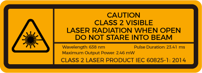
DO NOT look into the laser beam or the reflected laser beam directly. Do not look into the laser beam with optical instruments. Failure to do so may lead to eye injuries. DO NOT direct the laser at other people.
-
The laser beam must be lower or higher than and never at eye level.
-
Be cautious of the path of the laser beam. If there is a possibility that personnel may be exposed to the specular or diffuse reflections, block the beam by installing a protective enclosure. Do not enter the areas that the laser/reflected laser output reaches. Do not place any reflective light object (mirror, glass, metal, etc.) in the path of the laser beam.
-
LASER ENERGY - EXPOSURE NEAR APERTURE MAY CAUSE BURNS. NOTE: The risk of skin injury is only likely for highly divergent beams for exposure close to the aperture.
Notice for Disposal
-
Please comply with local laws and regulations when disposing of the camera to avoid polluting the environment. Please do not dispose of the camera irresponsibly. Improper disposal may pollute the environment.
![]() This icon indicates that failure to follow the instruction may lead to injury or death.
This icon indicates that failure to follow the instruction may lead to injury or death.
Certifications
Mech-Eye Industrial 3D Camera is compliant with the following standards and assessment requirements. Please note that the registration statuses may be updated. If you need more information, please contact the local agents.
CE
Compliant with the following European Electromagnetic Compatibility Standards:
-
EN55032: 2015+A11: 2020
-
EN IEC 61000-3-2: 2019+A1: 2021
-
EN 61000-3-3: 2013+A1: 2019
-
EN 55035: 2017+A11: 2020


Cables and Accessories
Ethernet cable |
Adapter |
AC power cable |
|---|---|---|
|
|
|
DIN rail power supply |
DC power cable |
Calibration board |
|
|
|


|
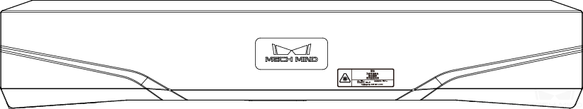
Functional Diagram

| The above figure is for reference only. The actual product may differ. |
No. |
Name |
Function |
|
|---|---|---|---|
① |
DC 24V port |
1: GND |
2: GND |
3: 24 VDC |
4: 24 VDC |
||
② |
ETH port |
1: MD3_P |
2: MD2_N |
3: MD2_P |
4: MD0_P |
||
5: MD1_P |
6: MD0_N |
||
7: MD3_N |
8: MD1_N |
||
③ |
PWR indicator light |
Off: not connected to power |
|
Green: normal voltage |
|||
Yellow: abnormal voltage, but system is still functioning |
|||
Red: voltage too high or too low, system power is disconnected |
|||
④ |
LINK indicator light |
Off: not connected to network |
|
Blinking green: data being transmitted |
|||
Solid green: no ongoing data transmission |
|||
⑤ |
SYS indicator light |
Off: system not started |
|
Solid green: system starting up |
|||
Blinking green: system operating properly |
|||
Blinking yellow: system operating with error but still functioning |
|||
Blinking red: system not operating |
|||
⑥ |
SCAN indicator light |
Solid: capturing and processing in progress |
|
Off: not capturing or processing |
|||
Mount the Camera
| When mounting the camera, please prepare bolts, nuts and wrench of appropriate specifications according to the Dimensions section of Technical Specifications. |


Connect the Camera
|
Ethernet Cable
As shown below, insert the M12-A connector of the Ethernet cable to the ETH port on the camera, and insert the RJ45 connector to the Ethernet port on the computer.
DC Power Cable
As shown below, insert the M12-A connector of the DC power cable to the DC 24V port on the camera.

Connect the M12-A connectors of the cables to the corresponding ports:

-
When inserting, align the bump in the connector with the notch in the port.
-
Tighten the nut. A gap of about 2 mm remains after the nut is fully tightened.
DIN Rail Power Supply

When wiring the DIN rail power supply, wires of the power cable must be inserted to the corresponding input/output terminals, as shown above.
-
The AC power cable has three wires: L, N, and PE (
 ).
). -
The 24 V DC power cable has three wires: V+, V- and PE (
).
![]() Warning
Warning
The PE wires must be properly grounded! Please install the DIN rail power supply inside a control cabinet.
| A network switch can be used to connect multiple cameras or computers. |
Technical Specifications
Product name |
Mech-Eye Industrial 3D Camera |
|---|---|
Model |
LSR L |
Recommended working distance |
1200–3000 mm |
FOV (near) |
1200 × 1000 mm @ 1.2 m |
FOV (far) |
3000 × 2400 mm @ 3.0 m |
Depth map resolution |
2048 × 1536 |
RGB resolution |
4000 × 3000 / 2000 × 1500 |
Point Z-value repeatability (σ)(1) |
0.5 mm @ 3 m |
Measurement accuracy (VDI/VDE)(2) |
1.0 mm @ 3 m |
Typical capture time |
0.5–0.9 s |
Weight |
About 2.9 kg |
Baseline |
About 380 mm |
Dimensions |
About 459 × 77 × 86 mm |
Light source |
Red laser (638 nm, class 2) |
Operating temperature |
-10–45°C |
Communication interface |
Gigabit Ethernet |
Input |
24 VDC, 3.75 A |
Safety and EMC |
CE/FCC/VCCI/UKCA/KC |
IP rating(3) |
IP65 |
Cooling |
Passive |
(1) One standard deviation of 100 Z-value measurements of the same point. The measurement target was a ceramic plate.
(2) According to VDI/VDE 2634 Part II.
(3) Test implemented based on IEC 60529. 6: dust-tight; 5: protected against water jets.


Maintenance
Cleaning the Camera
When cleaning the surface of the camera, please blow off the dust gently, and then use a clean soft cloth to gently wipe the surface. When cleaning the camera lenses, a liquid lens cleaner and clean lint-free cloth can be used to carefully wipe the lenses to avoid scratching.
![]() Warning
Warning
-
Do not clean the camera with corrosive or volatile solvents such as alcohol, gasoline and kerosene. These substances may damage the exterior and internal structure of the camera.
-
Do not use a pressure washer gun or hose to spray and wash the camera. Water entering the camera may lead to malfunction, fire, or even explosion. Water or other liquid damage to the camera is not covered by the warranty.
Storing the Camera
This product is rated as IP65. The enclosure of the camera can prevent dust from entering and affecting the functions of the camera. Soaking the camera in water or placing it in a highly humid environment may lead to malfunction. Rusting of the internal unit will lead to irreversible damage. When not using, please store the camera in an indoor, dry, cool and well ventilated place. To avoid damage caused by rain, snow, and other undesirable conditions, please do not place the camera outdoors for an extended period of time.
![]() Warning
Warning
-
Disconnect the camera from the power supply when storing to avoid fire.
-
Do not leave the lens pointed at the sun or other intense light source for an extended period of time. Intense light may cause the image sensor to deteriorate and produce a white blur effect in images.
![]() This icon indicates that failure to follow the instruction may lead to injury or death.
This icon indicates that failure to follow the instruction may lead to injury or death.
Trademark and Legal Statement
Mech-Mind and Mech-Mind series logos including ![]() are registered trademarks of Mech-Mind Robotics Technologies Ltd. (“Mech-Mind”) and other related entities.
are registered trademarks of Mech-Mind Robotics Technologies Ltd. (“Mech-Mind”) and other related entities.
Unless authorized in writing in advance by Mech-Mind, no part of the trademarks shall be used, reproduced, modified, transmitted, transcribed, or used or sold with other products as a bundle by any entity or individual in any form for any reason.
Any infringement of Mech-Mind’s trademark rights will be punished in accordance with the law.
Mech-Mind reserves all rights regarding this user manual. According to copyright laws, unless authorized in writing by Mech-Mind, this user manual shall not be reproduced, modified, reprinted or issued in part or in its entirety by any entity or individual. Users who purchased and use the product may download, print or copy the user manual for personal use or use inside the belonging organization. Unless authorized in writing by Mech-Mind, the contents of the user manual may not be used for any other purposes. Unless authorized in writing by Mech-Mind, this manual cannot be reprinted or reproduced wholly or in part by any company or individual.