PROFINET
Mech-MSR can communicate with external devices by using the PROFINET protocol. Before you read the following content, make sure that the communication configuration has been completed in Mech-MSR.
About PROFINET
Mech-MSR can communicate with a PLC by using the PROFINET protocol. Under this communication mode, Mech-MSR acts as the server (slave) and the PLC acts as the client (master). The PLC actively initiates requests to control Mech-MSR and read or write data, while Mech-MSR passively responds to requests, providing measurement and inspection results.
| Mech-MSR supports PROFINET communication with the PLC only through a hardware communication card. You need to install an HMS Ixxat INpact EIP Slave PCIe communication card on the IPC (prepared or purchased by yourself) and flash the card with the PROFINET protocol. |
Communication Workflow
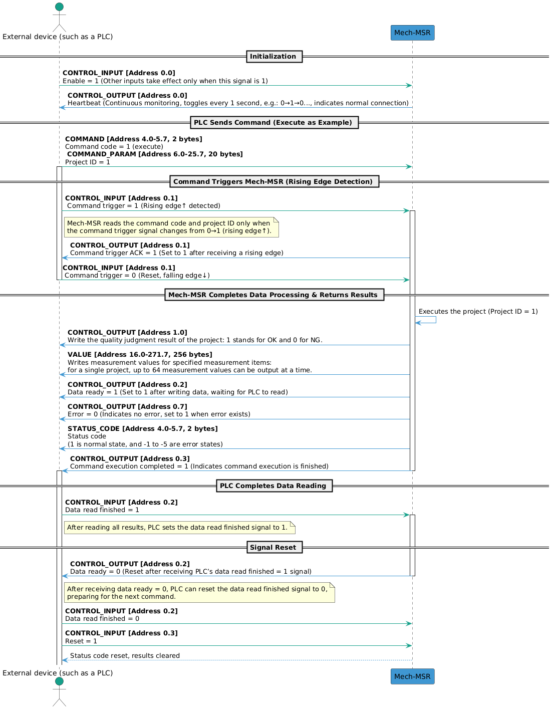
The workflow of PROFINET communication is shown in the figure below.
| You can check the table in Input and Output Signals to learn the meaning of each signal. |
Input and Output Signals
| Input (from the PLC to Mech-MSR) | Output (from Mech-MSR to the PLC) | ||||
|---|---|---|---|---|---|
Module |
Name |
Bytes occupied |
Module |
Name |
Bytes occupied |
Command enable |
1 byte |
Heartbeat |
1 byte |
||
Command trigger |
Trigger acknowledge |
||||
Data read finished |
Data ready |
||||
Reset |
Execution completed |
||||
Reserved field |
Reserved field |
||||
Reserved field |
Reserved field |
||||
Reserved field |
Reserved field |
||||
Reserved field |
Error |
||||
Reserved field |
3 bytes |
Overall judge |
1 byte |
||
Reserved field |
|||||
Reserved field |
|||||
Reserved field |
|||||
Reserved field |
|||||
Reserved field |
|||||
Reserved field |
|||||
Reserved field |
|||||
Reserved field |
2 bytes |
||||
Command code |
2 bytes |
Status code |
2 bytes |
||
Command parameter 1 |
2 bytes |
RESERVED |
Reserved field |
2 bytes |
|
Command parameter 2 |
2 bytes |
Judgment result of ID 1 Judgment result of ID 2 Judgment result of ID 3 ... |
8 bytes |
||
Command parameter 3 |
2 bytes |
||||
Command parameter 4 |
2 bytes |
||||
Command parameter 5 |
2 bytes |
||||
Command parameter 6 |
2 bytes |
Measurement result of ID 1 Measurement result of ID 2 Measurement result of ID 3 ... |
256 bytes (4 bytes × 64) |
||
Command parameter 7 |
2 bytes |
||||
Command parameter 8 |
2 bytes |
||||
Command parameter 9 |
2 bytes |
||||
Command parameter 10 |
2 bytes |
||||
Variable 1 |
4 bytes |
||||
Variable 2 |
4 bytes |
||||
Variable 3 |
4 bytes |
||||
Variable 4 |
4 bytes |
||||
Variable 5 |
4 bytes |
||||
Variable 6 |
4 bytes |
||||
Variable 7 |
4 bytes |
||||
Variable 8 |
4 bytes |
||||
Variable 9 |
4 bytes |
||||
Variable 10 |
4 bytes |
||||
Input (from the PLC to Mech-MSR)
CONTROL_INPUT
| Address | Data | Description |
|---|---|---|
0.0 |
Command enable (Boolean) |
Only when the command enable signal is set to 1, other input signals take effect. |
0.1 |
Command trigger (Boolean) |
When the command trigger signal changes from 0 to 1 (a rising edge is detected), Mech-MSR reads command codes and command parameters. When Mech-MSR returns the trigger acknowledge signal, the command trigger signal can be set to 0. |
0.2 |
Data read finished (Boolean) |
When the PLC completes data reading, this signal will be set to 1. When the PLC is informed that the data ready signal changes to 0, this signal can be set to 0. |
0.3 |
Reset (Boolean) |
When this signal is set to 1, the PLC clears the received judgement result and measurement result. At this point, the PLC can send new commands and status code signals are reset. |
0.4 |
Reserved field (Boolean) |
A reserved field. |
0.5 |
Reserved field (Boolean) |
A reserved field. |
0.6 |
Reserved field (Boolean) |
A reserved field. |
0.7 |
Reserved field (Boolean) |
A reserved field. |
1.0–3.7 |
Reserved field (Byte) |
A reserved field. |
COMMAND & COMMAND_PARAM
The following table lists the supported commands in the current protocol and their corresponding command codes (COMMAND), command parameters (COMMAND_PARAM), and descriptions:
| Command | COMMAND | COMMAND_PARAM | Description |
|---|---|---|---|
execute |
1 |
Project ID. Only one project ID can be set each time. |
Used to trigger the project and obtain project judgement result and measurement result. |
trigger |
2 |
Project ID. One to four project IDs can be set at a time. |
Used to trigger one or multiple projects to run. |
return |
3 |
Project ID. Only one project ID can be set each time. |
Used to obtain the judgement result and the measurement result of the specified project. |
judge |
4 |
Used to obtain the overall quality judgment result of the specified project or the judgment results of individual measurement items. |
|
value |
5 |
Used to obtain the measured values of the specified project. |
|
recipe |
6 |
Project ID, parameter recipe ID |
Used to switch the parameter recipe used by the project. |
solution |
7 |
Solution ID. |
Used to switch the solution. |
SetNumVar |
8 |
Global variable ID. Only one ID can be set at a time. |
Used to set the value of a numeric global variable. The variable value is passed through VAR_INPUT. |
GetNumVar |
9 |
Global variable ID. Only one ID can be set at a time. |
Used to read the value of a numeric global variable. The result is returned through VALUE. |
|
VAR_INPUT
When SetNumVar is executed, the set value is set to VAR_INPUT.
| Address | Data | Description |
|---|---|---|
26.0–29.7 |
Variable 1 (Float) |
The numeric input parameter is 1. |
30.0–33.7 |
Variable 2 (Float) |
The numeric input parameter is 2. |
34.0–37.7 |
Variable 3 (Float) |
The numeric input parameter is 3. |
38.0–41.7 |
Variable 4 (Float) |
The numeric input parameter is 4. |
42.0–45.7 |
Variable 5 (Float) |
The numeric input parameter is 5. |
46.0–49.7 |
Variable 6 (Float) |
The numeric input parameter is 6. |
50.0–53.7 |
Variable 7 (Float) |
The numeric input parameter is 7. |
54.0–57.7 |
Variable 8 (Float) |
The numeric input parameter is 8. |
58.0–61.7 |
Variable 9 (Float) |
The numeric input parameter is 9. |
62.0–65.7 |
Variable 10 (Float) |
The numeric input parameter is 10. |
Output (from Mech-MSR to the PLC)
CONTROL_OUTPUT
| Address | Data | Description |
|---|---|---|
0.0 |
Heartbeat (Boolean) |
System heartbeat. It toggles every second. Used to determine whether the PLC and Mech-MSR are connected or disconnected. |
0.1 |
Trigger acknowledge (Boolean) |
When Mech-MSR receives the rising edge for the command trigger signal, this signal is set to 1. When a falling edge is detected for the command trigger signal, this signal is set to 0. |
0.2 |
Data ready (Boolean) |
Mech-MSR writes data to output ports and waits for the PLC to read the output data. When the data read signal is set to 1, this signal is set to 0. |
0.3 |
Execution completed (Boolean) |
When the command execution completes, this signal is set to 1, which indicates that the command execution is completed. |
0.4 |
Reserved field (Boolean) |
A reserved field. |
0.5 |
Reserved field (Boolean) |
A reserved field. |
0.6 |
Reserved field (Boolean) |
A reserved field. |
0.7 |
Error (Boolean) |
If the status code returned by Mech-MSR is not 1, an error occurred and this signal is set to 1. |
1.0 |
Overall judge (Boolean) |
The overall judgement of the project. 1 indicates OK, and 0 indicates NG. |
1.1–1.7 |
Reserved field (Boolean) |
A reserved field. |
2.0–3.7 |
Reserved field (Byte) |
A reserved field. |
STATUS_CODE
The possible returned status codes for Mech-MSR are as follows:
-
Normal status code: 1, indicating that the command was executed successfully.
-
Error codes: -1, -2, -3, -4, -5. For more information, see Error Codes.
JUDGE
Judgement results were added for measurement items on the Communication output tab in the Output Management window. 1 indicates OK, and 0 indicates NG.
| At most 64 judgement results can be output for a single project at a time. |
VALUE
The VALUE module returns the following data:
-
Measurement results are added for measurement items on the Communication output tab in the Output Management window.
-
The values of numeric global variables are read when the
GetNumVarcommand is executed.
| At most 64 measurement results can be output for a single project at a time. |