Hand-Eye Calibration
In this tutorial, you will perform the automatic hand-eye calibration in the eye-to-hand setup.
|
The hand-eye calibration establishes the transformation relationship between the camera and robot reference frames (that is camera extrinsic parameters). With this relationship, the object pose determined by the vision system can be transformed into that in the robot reference frame, which guides the robot in performing its tasks. |
Video Tutorial: Hand-Eye Calibration (Standard Interface Communication)
|
Preparation before Calibration
In this section, you will modify the robot calibration program, mount the calibration board, adjust camera parameters, and perform pre-calibration configuration.
Modify the Robot Calibration Program (MM_AUTO_CALIB)
Select the Calibration Program
-
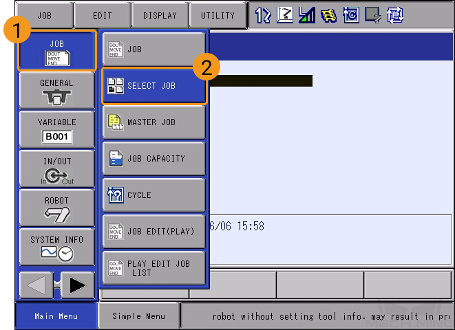
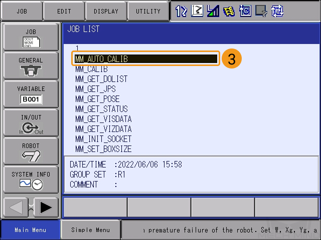
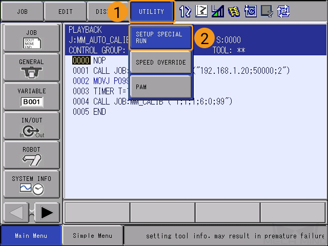
In the TEACH mode, select . Move the cursor to MM_AUTO_CALIB in the JOB LIST and press the SELECT key on the teach pendant.
-
The interface is as follows after the program file is selected.
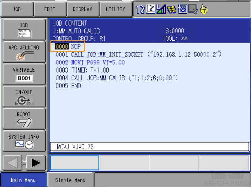
| You have already modified the IP address and port of the IPC in the section Test Standard Interface Communication. Therefore, you just only need to teach the calibration start point in this tutorial. |
Teach the Calibration Start Point
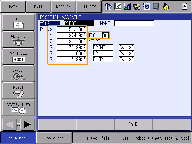
| In the calibration process, the robot poses sent by the robot to Mech-Vision must be flange poses. Therefore, before this step, you need to switch the tool No. to that (usually 00) of the tool whose ToolOffset values are all 0. The Tool Center Point (TCP) of Tool00 is at the center of the flange. |
-
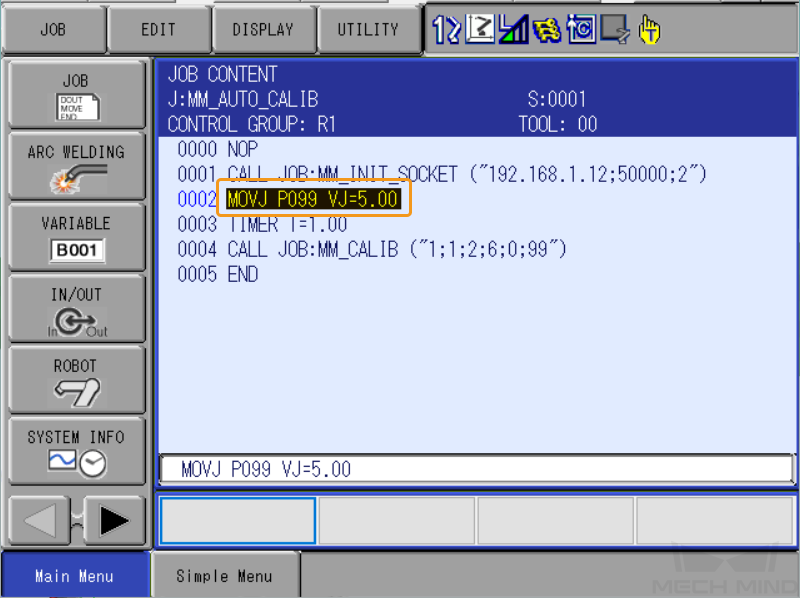
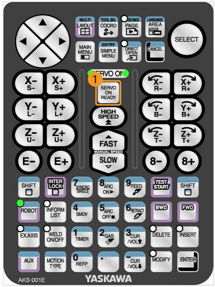
Move the robot to the start point for calibration. Move the cursor to MOVJ P099 VJ=5, and press the DIRECT OPEN key on the teach pendant.
-
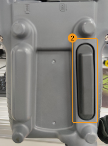
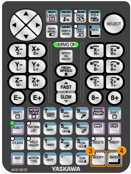
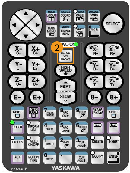
Change the value of P099 to the current pose of the robot: Press the SERVO ON READY key on the teach pendant. Press the MODIFY key and then the ENTER key while holding the enable switch on the back. Make sure the value for TOOL is 00.
-
Press the DIRECT OPEN key on the teach pendant again to return to JOB CONTENT.
So far, you have successfully modified the calibration program necessary for the automatic calibration process of YASKAWA robots.
Mount the Calibration Board
|
In the eye-to-hand setup, the calibration board needs to be mounted to the robot flange adapter. |
Follow these steps:
-
Take the calibration board and flange adapter out of the camera delivery package.
-
Use screws, gaskets, and nuts to fasten the flange adapter to the flange adapter.
-
Use screws, gaskets, and nuts to secure the calibration board to the flange adapter. The calibration board is parallel to the XY plane at the robot end.
-
After mounting, move the robot to the starting point for calibration, i.e., the top surface of the lowest workpiece in the workspace and at the center of the camera’s field of view. The robot will move the calibration board upwards during calibration.
Adjust Camera Parameters
-
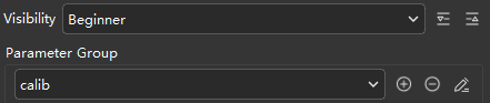
Connect to the camera in Mech-Eye Viewer , and select the calib parameter group in the Parameter Group drop-down list.
-
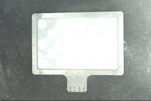
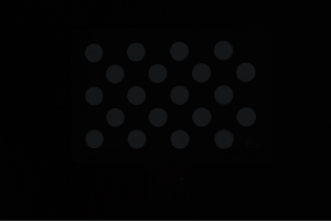
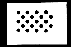
Adjust the 2D parameters to make sure that the 2D image of the calibration board is clear and neither overexposed nor underexposed.
Normal Overexposed Underexposed 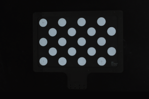
-
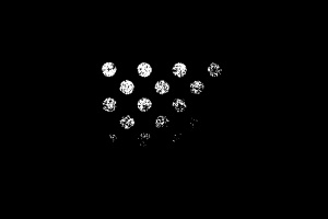
Adjust 3D parameters to make sure that the obtained point clouds of the circles on the calibration board are complete and have clear contours. It is recommended to set the Surface Smoothing and Outlier Removal parameters of Point Cloud Processing to Normal to reduce point cloud fluctuation.
Point cloud complete Point cloud incomplete Point cloud incomplete 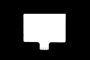
Pre-calibration Configuration
-
In Mech-Vision, click the Camera Calibration (Standard) button on the toolbar to open the Pre-calibration Configuration window.
-
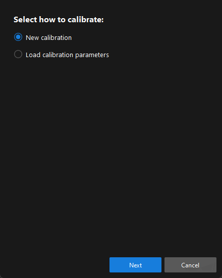
In the Select how to calibrate window, select the New calibration radio button, and then click the Next button.
-
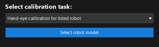
In the Select calibration task window, select Hand-eye calibration for listed robot from the drop-down list box, and click the Select robot model button.
-
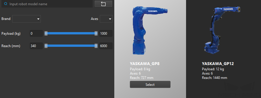
Click the Brand dropdown box, and select “YASKAWA”. Then, at the right panel, select model “YASKAWA_GP8”, click the Select button, and then click the Next button.
-
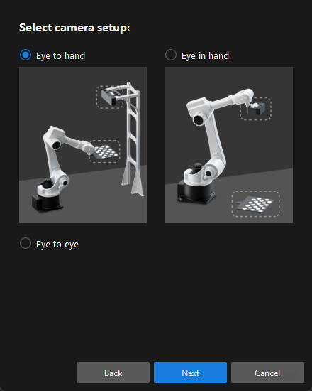
In the Select camera setup window, select the Eye to hand radio button, and then click the Next button.
-
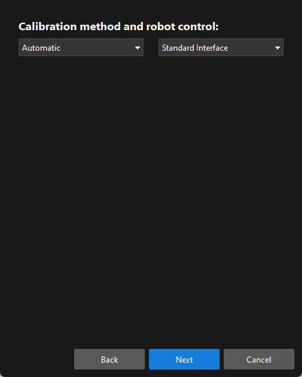
In the Calibration method and robot control window, select Automatic and Standard Interface, and then click the Next button.
-
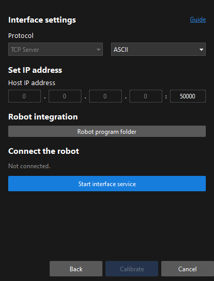
In the Pre-calibration Configuration window, keep the default value for Protocol. Click the Start interface service button in the Connect the robot area, and the message on this button will change to Waiting for the robot to connect....
-
In this tutorial, the vision system acts as the TCP server. Therefore, the Host IP address parameters should be set to the IP address and port of the IPC. Since the IP address of the IPC is a local IP address, you do not need to set it and the software uses “0.0.0.0” to indicate it.
-
By default, the IPC uses port 50000 to provide the interface service. You can change the port number as required. If you have changed the port number, remember to use the correct port number when you try to establish communication with the vision system on the robot side.
-
Run the Calibration Program
-
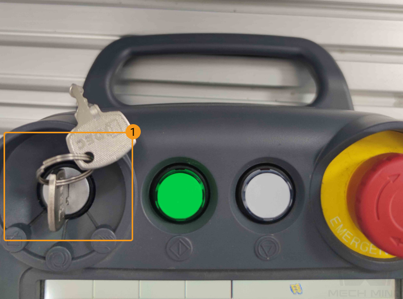
Move the cursor back to line 0000, turn the mode switch to REPEAT mode, and press SERVO ON READY key on the teach pendant .
-
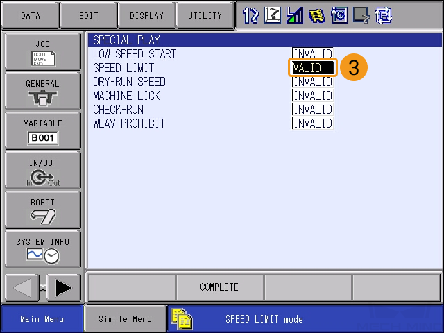
To move the robot at a low speed, select on the teach pendant screen, and change SPEED LIMIT to VALID.
-
Press the green START button on the teach pendant. when the start LED is lit, the robot is running the program.
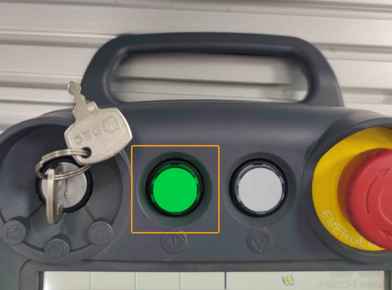
In case of emergency, press pause oremergency stop immediately. -
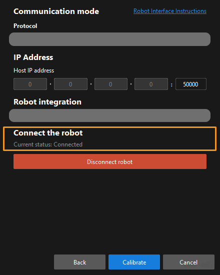
When, in the Configuration before Calibration window in Mech-Vision, the current status changes to connected and the button “Waiting for the robot to connect” changes to “Disconnect”, click Calibrate. The Calibration (Eye to hand) window will be prompted.
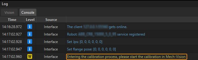
If the robot is connected successfully, the Console tab of Mech-Vision Log panel will display a log.
Calibration Procedure
Connect to a Camera
-
In the Connect to Camera step, find the camera to connect in the Detected Cameras list, and click the
 button.
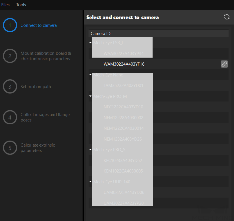
-
After the camera is connected, click the Capture once or Capture live button.
-
In the right Image viewer panel, ensure that the captured 2D image and point cloud meet the calibration requirements and click the Next button on the bottom bar.
|
If the captured image does not meet the calibration requirements, you need to open the Mech-Eye Viewer software to adjust the 2D and 3D exposure parameters and re-capture images. |
Mount Calibration Board & Check Intrinsic Parameters
-
In the Mount calibration board & check intrinsic parameters step, select the calibration board model for the Standard calibration board model parameter according to its model nameplate in the 1 Select calibration board area.

-
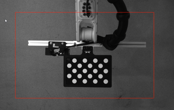
In the 2 Check calibration board position and point cloud quality area, read carefully the requirements on the calibration board position and point cloud quality, and then click the Capture live button. The Capture live button will turn into Stop capturing and detect position.
-
Control the robot to move the calibration board to the proper position, and ensure that the 2D image and depth map of the calibration board meet the requirements, and then click the Stop capturing and detect position button.
-
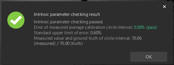
In the 3 Check intrinsic parameters area, click the Check intrinsic parameters button.
-
Confirm the results of the camera intrinsic parameter check.
-
If the camera intrinsic parameter check passes, click the OK button in the prompted window, and then click the Next button on the bottom bar.
-
If the intrinsic parameter check fails, adjust the calibration circle detection parameters by drawing aid circles or modifying detection parameters, and then click the Check intrinsic parameters button.
-
| If the camera still cannot pass the intrinsic parameter check after the above operations, the intrinsic parameters of the camera may be problematic and need to be corrected, or contact Mech-Mind Technical Support. |
Set Robot Path
-
In the Set robot path step, set the Height span parameter in the 1 Set height span of calibration poses area.
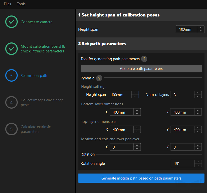
The Height span parameter should be set according to the recommended working distance range of the camera and the size of the robot’s working space.
-
Click the Generate path parameters button, and click the OK button in the prompted window.
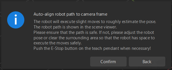
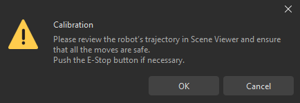
This operation will slightly move the robot and capture images. The whole process may take 10 to 15 seconds. Please ensure that the robot path is safe. In case of emergency, please tap the emergency stop button on the robot teach pendant to stop the robot immediately. -
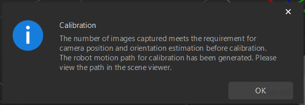
In the prompted Calibration window, click the OK button.
-
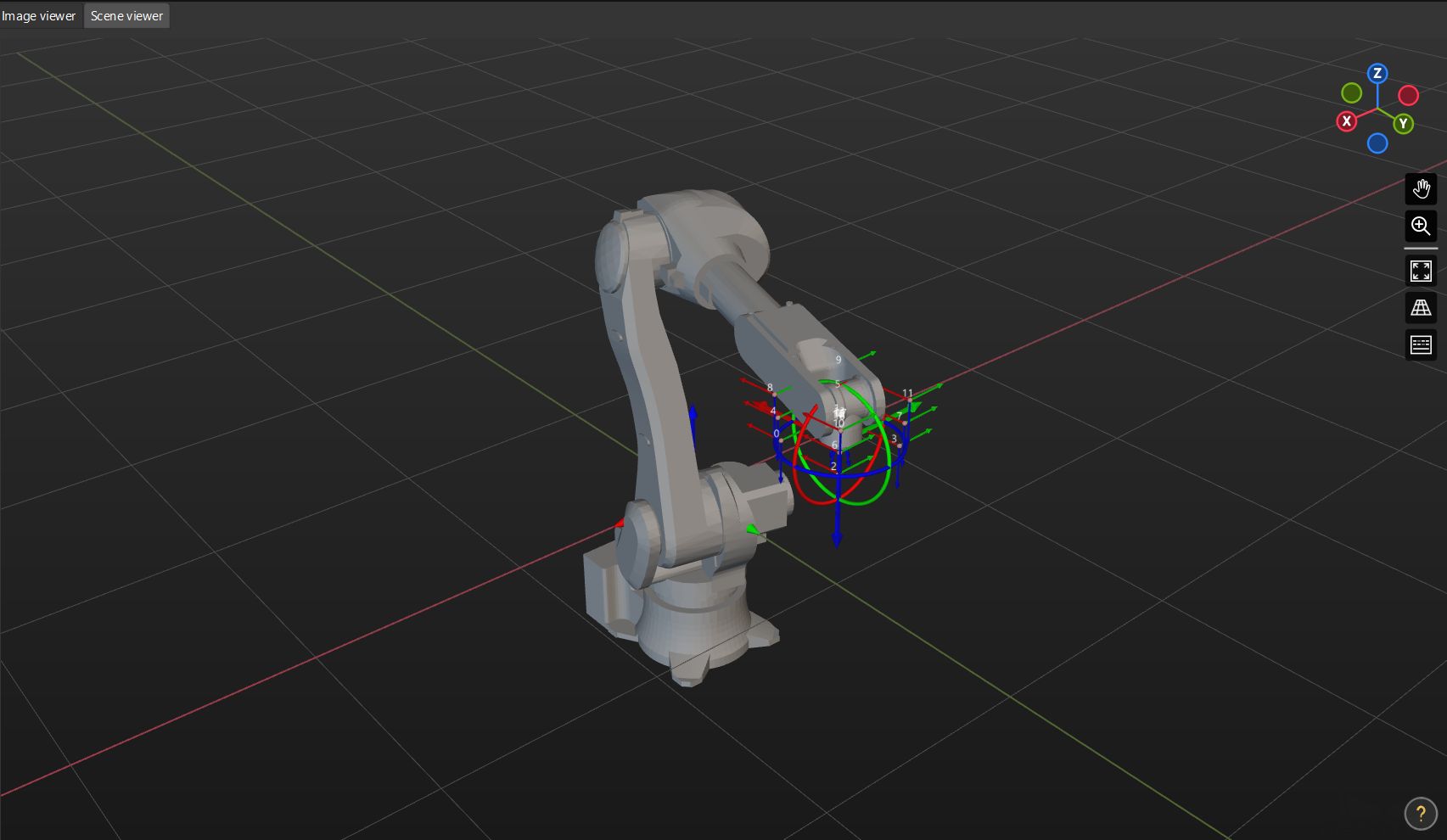
In the right Scene viewer panel, confirm that waypoints are reasonable and will not collide with obstacles.
-
Click the Generate robot path based on path parameters button and then click the Next button on the bottom bar.
Collect Images and Flange Poses
-
In the Collect images and flange poses step, select the Save images checkbox.
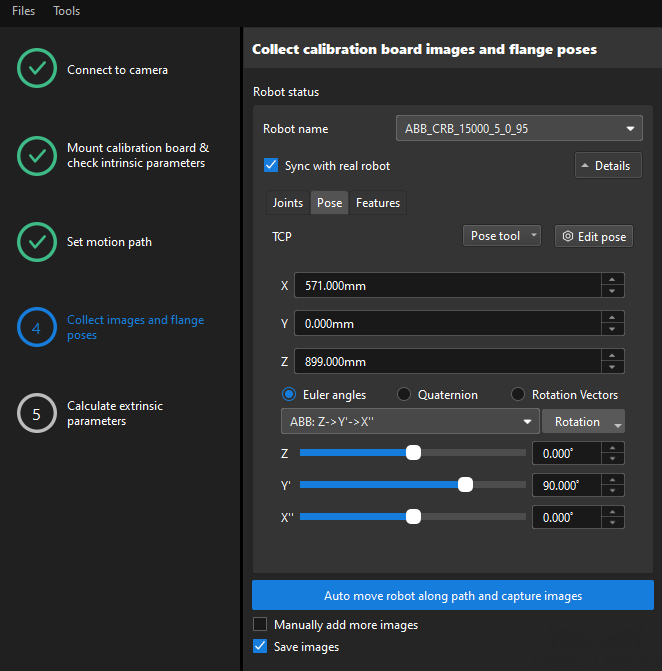
-
Click the Control robot to auto move along path and capture images button.
-
Read the safety window carefully and click the OK button.
-
Wait until the robot finishes moving along the preset path and the camera finishes capturing images on all waypoints. Captured images can be seen in the right Marker Image and Pose List panel during this process.
-
Please stay away from the robot working area to keep safe.
-
Clicking the Stop robot button can exit the calibration process. But the robot will not stop until it finishes the current waypoint. In case of emergency, please tap the emergency stop button on the robot teach pendant to stop the robot immediately (the robot needs to be reconnected after tapping the emergency stop button).
-
-
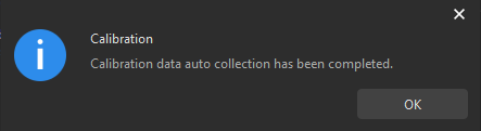
After the automatic image capturing finishes, click OK in the pop-up window.
-
Confirm that the collected calibration data meets the data requirements, and then click the Next button on the bottom bar.
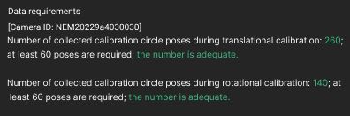
If the requirements are not met, please manually move the robot (through the teach pendant or Mech-Viz), select the Manually add more images checkbox, and click the Add an image and record flange pose button to add the calibration board image and enter the robot flange pose.
Calculate Extrinsic Parameters
-
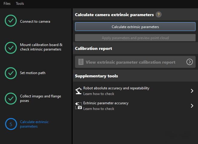
In the Calculate extrinsic parameters step, click the Calculate extrinsic parameters button.
-
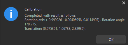
In the prompted window indicating calibration success, click the OK button.
-
Click the View extrinsic parameter calibration report button. The extrinsic parameter calibration report will be automatically displayed after it is generated.
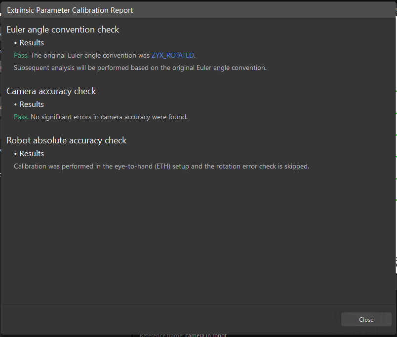
The extrinsic parameter calibration report displays the results of the Euler angle convention check, camera accuracy check, and robot absolute accuracy check. -
Confirm the results of the Euler angle convention check, camera accuracy check, and robot absolute accuracy check in the report, and then click the Close button to close the report.
-
If the camera accuracy in the report does not meet the requirements, please follow the recommendation to troubleshoot the camera accuracy errors. If you want to enhance the calibration accuracy, please refer to the section Calibration Result Check and Analysis.
-
To evaluate the robot absolute accuracy and the accuracy of calculated extrinsic parameters, you can click Robot absolute accuracy and repeatability and Extrinsic parameter accuracy in the “Calculate extrinsic parameters” window and use the error analysis tool to perform robot absolute accuracy check and analyze extrinsic parameter error in ETH setup.
-
-
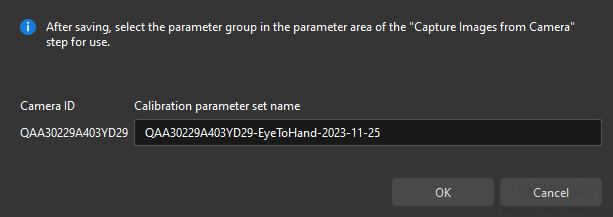
Click the Save button on the bottom bar. In the prompted Save Calibration Files dialog box, click the OK button. The camera calibration result will be automatically saved in the “calibration” directory of the project.
Now you have completed the hand-eye calibration in the eye-to-hand setup.