Workpiece Locating
Before using this tutorial, you should have created a Mech-Vision solution using the General Workpiece Recognition case project in the Robot Communication Setup section.
In this tutorial, you will first learn the project workflow, and then deploy the project by adjusting the Step parameters to recognize the workpieces’ poses and output the vision result.
Video Tutorial: Workpiece Locating
|
| In this project, every time the Mech-Vision is run, a vision point will be output. |
Introduction to the Project Workflow
The following table describes each Step in the project workflow.
| No. | Phase | Step | Image | Description |
|---|---|---|---|---|
1 |
Capture images |
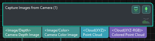
Capture Images from Camera |
|
Connect to the camera and capture images |
2 |
Recognize workpieces |
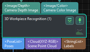
3D Workpiece Recognition |
|
Use 3D matching algorithms to calculate the workpieces’ poses (as pick points) |
3 |
Adjust poses |
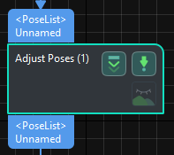
Adjust poses |
|
Transform the pick points from the camera reference frame to the robot reference frame |
4 |
Output the vision result |
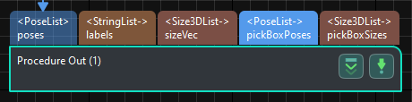
Procedure Out |
|
Output the workpieces’ poses for the robot to pick |
5 |
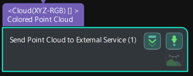
Send Scene Point Cloud |
Send Point Cloud to External Service |
|
Send the scene point cloud to the Mech-Viz for pick-and-place with the Mech-Viz |
|
A pick point refers to a point on the workpiece on which the robot can pick the object. |
Adjust Step Parameters
In this section, you will deploy the project by adjusting the parameters of each Step.
Capture Images from Camera
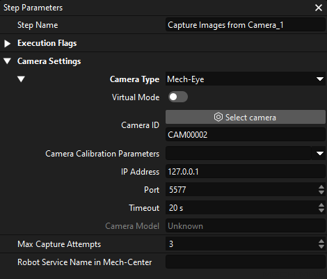
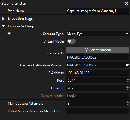
You should adjust the parameters of the Capture Images from Camera Step to connect to the camera.
-
Select the Capture Images from Camera Step, and click Select camera on the Step parameters tab.
-
In the pop-up window, click
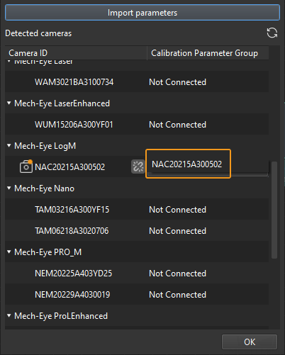
 on the right of the camera serial No. to connect the camera. After the camera is connected successfully, the icon will turn into
  .
.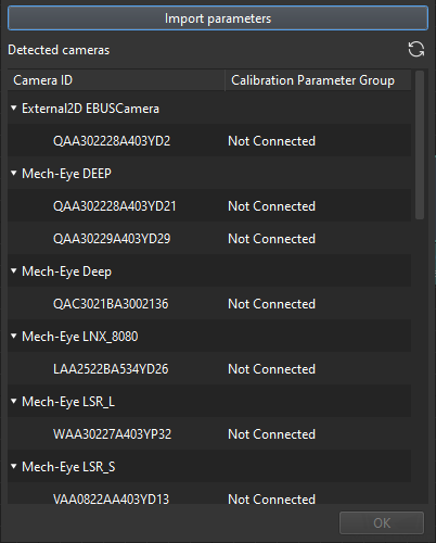
After the camera is connected, select the parameter group. Click the Select parameter group button and select the calibrated parameter group with ETH/EIH and date.
-
After the camera is connected and the parameter group is selected, the calibration parameter group, IP address, and ports of the camera will be obtained automatically. Just keep the default settings of the other parameters.
Now the camera is successfully connected.
3D Workpiece Recognition
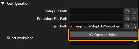
The “3D Workpiece Recognition” Step has integrated a 3D workpiece recognition visualized configurator, which provides point cloud preprocessing, model-based matching, and pose (pick point) calculation.
Select the 3D Workpiece Recognition Step, and click Open an Editor on the Step parameters tab.
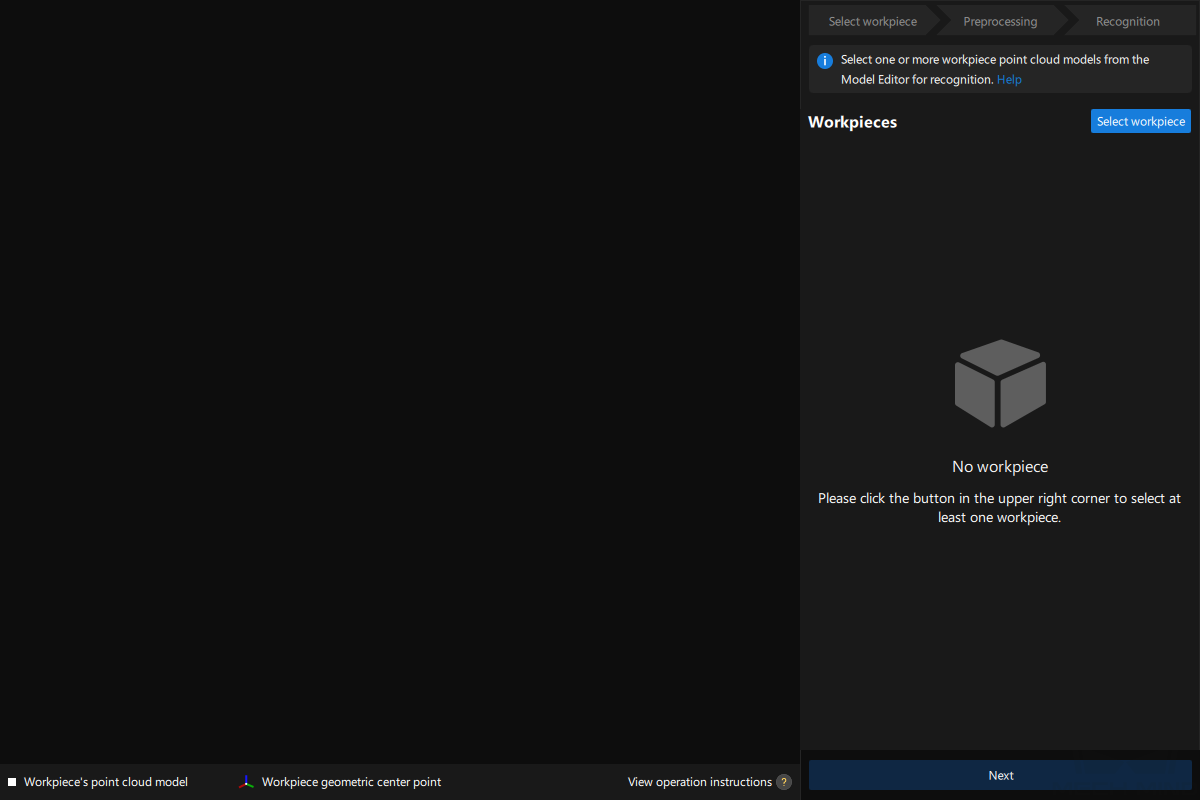
The 3D workpiece recognition visualized configurator is shown below.
Then follow the procedure to recognize workpieces.

Select Workpiece
After entering the 3D workpiece recognition visualized configurator, you need to make the point cloud model for the workpieces to recognize.
-
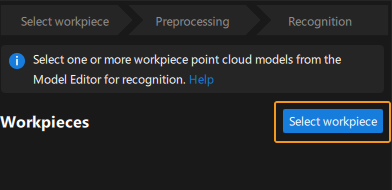
Open the Model Editor.
At the upper right corner of the 3D workpiece recognition visualized configurator, click Select workpiece.
In the pop-up Workpiece Library window, click the Model Editor button.
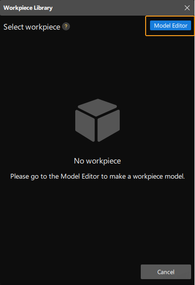
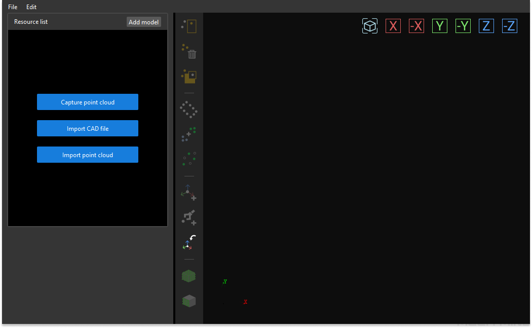
The following figure shows the Model Editor.
-
Generate the point cloud model by capturing point clouds.
-
Capture the depth map of the object.
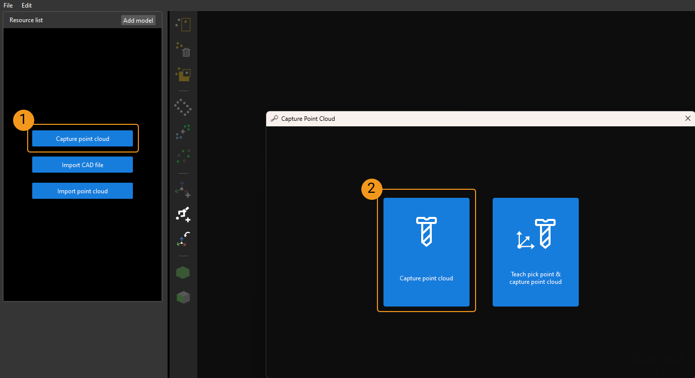
Click the Capture point cloud button in the start screen, and select Capture point cloud in the pop-up window.
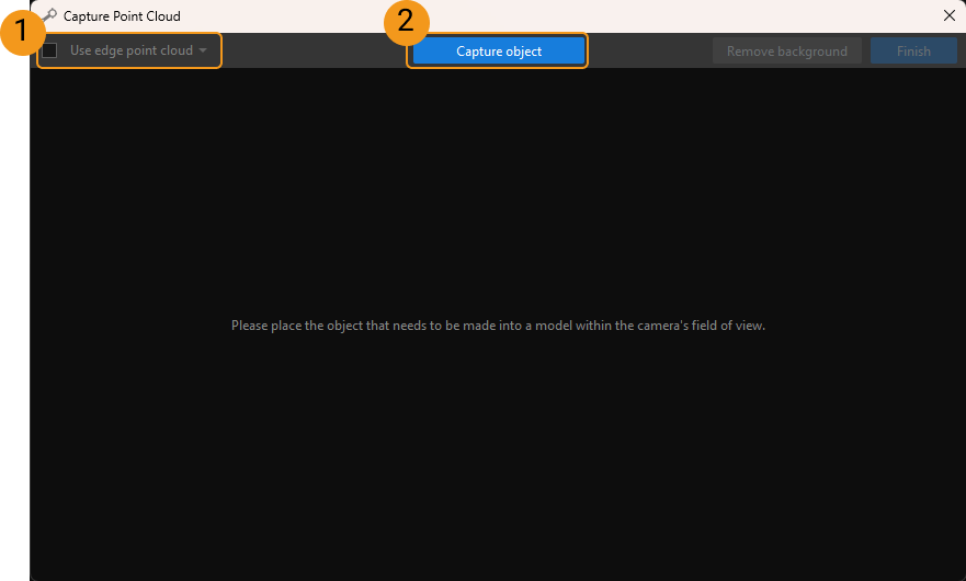
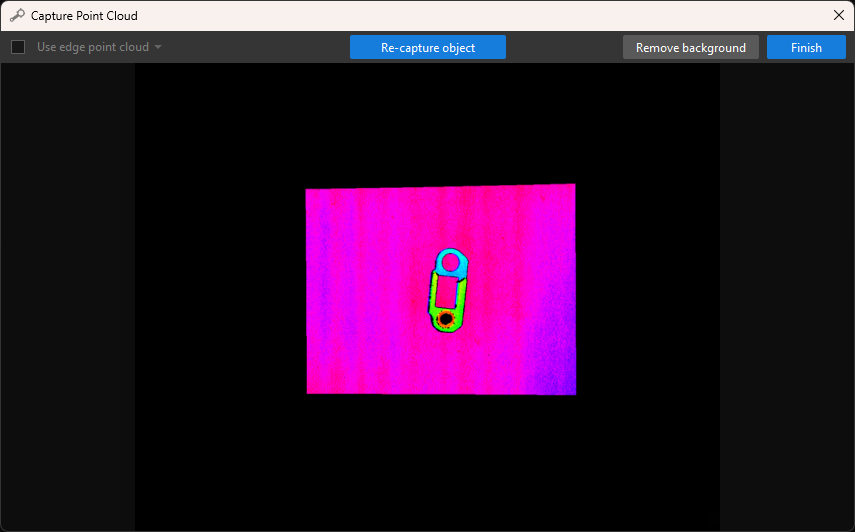
Due to the complex surface features of the track link, it is recommended to create a surface point cloud model for this workpiece. Therefore, clear the Use edge point cloud checkbox. Then click the Capture object button to capture the depth map of the target object.
The captured depth map of the target object and background is shown as below.
-
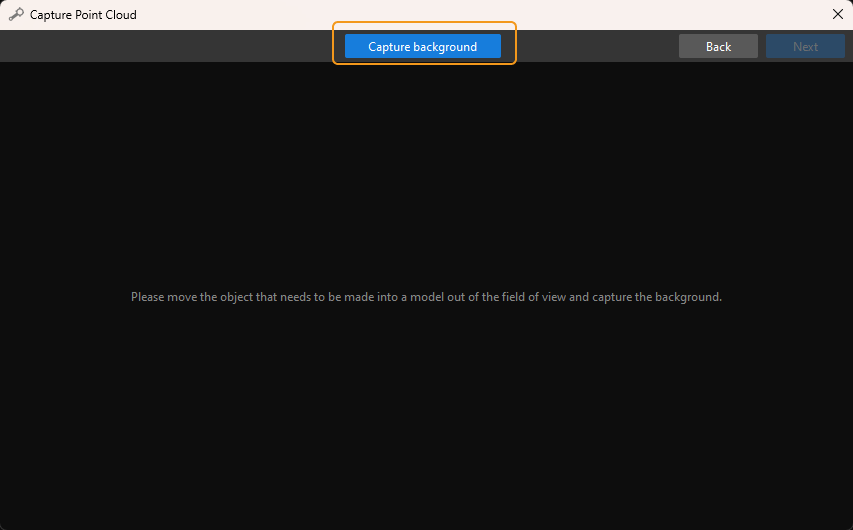
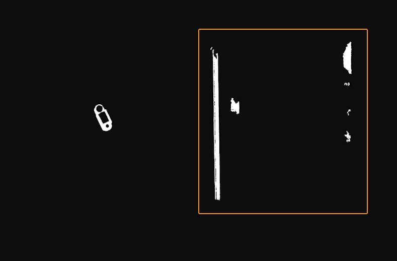
Capture background.
Click the Remove background button in the upper-right corner.

Remove the target object in the camera’s field of view first, and click Capture background again to capture a depth map of the background.
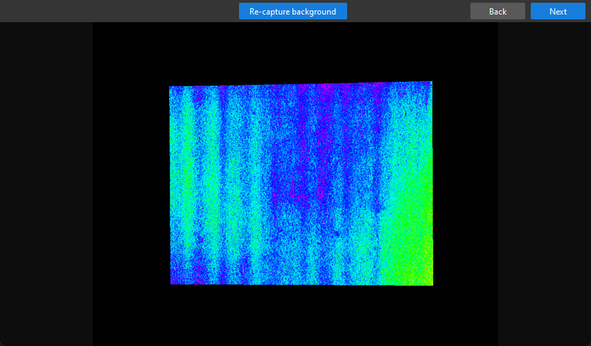
The depth map of the background is shown as below. Then, click the Next button in the upper-right corner.
-
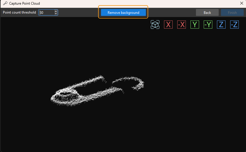
Subtract the background.
Click the Remove background button in this window to get the removed object. Then click the Finish button in the upper-right corner to import the removed object into Matching Model and Pick Point Editor.
-
-
Edit the point cloud model.
A generated point cloud model may not meet the actual requirement. In such case, you need to edit the model, including removing outliers and downsampling the point cloud.
-
Remove unwanted points.
Click the
 icon, select unwanted points to remove, and then click the
  icon to remove selected points.
As the figure above, selected points are unwanted points and can be removed by following this step.
-
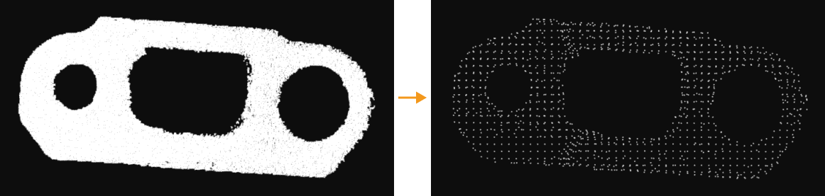
Downsample the point cloud.
Point cloud downsampling aims to reduce the number of points in the point cloud model, thus improving model matching efficiency.
Click the
 icon and set the sampling interval in the pop-up window.
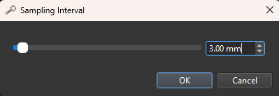
In the figure below, the left image is a point cloud model before downsampling, and the right one is after downsampling with a sampling interval of 3 mm.
-
-
Add a pick point.
Click the
 icon on the toolbar to add a pose as a pick point to the point cloud model of the workpiece.
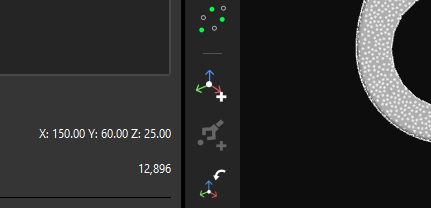
The following figure shows the added pick point.
-
Save the model and the pick point.
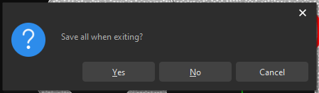
Close the Matching Model and Pick Point Editor, and click Yes in the pop-up window.
-
Select this workpiece from the Workpiece Library.
After closing the Matching Model and Pick Point Editor, select the saved point cloud model of the workpiece, and click OK.
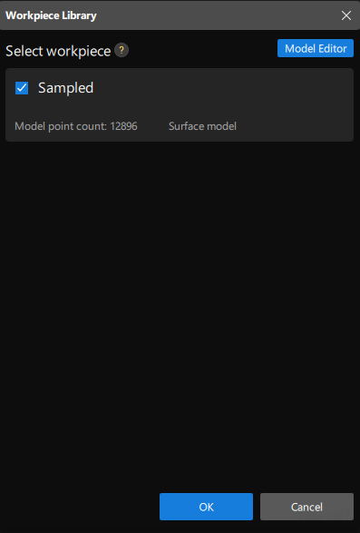
Subsequently, the target workpiece to recognize is displayed in the upper-right corner of the 3D workpiece recognition visualized configurator.
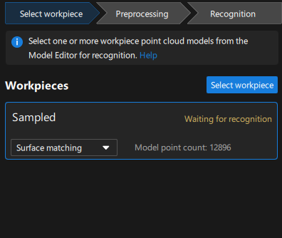
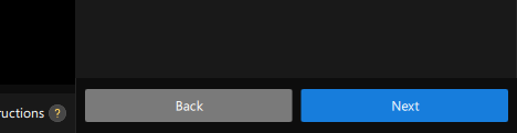
Now, you have selected the workpiece. Click Next on the bottom of the 3D workpiece recognition visualized configurator.
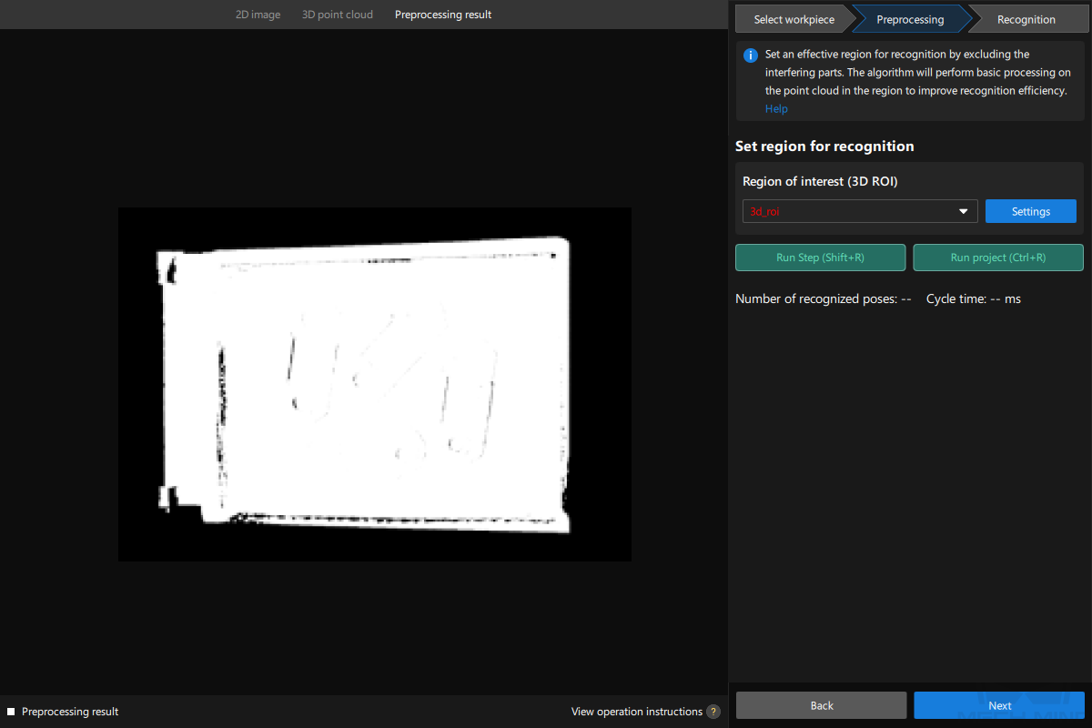
Preprocessing
Preprocessing is used to set an effective region for recognition to exclude the point cloud of unnecessary parts and keep only the point cloud of the workpiece, thus improving recognition efficiency.
The following figure displays the Preprocessing interface.
-
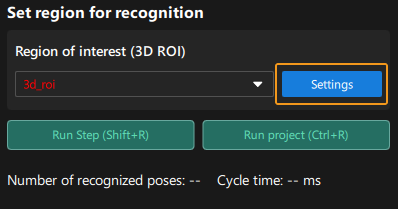
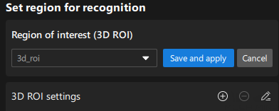
Set the region for recognition.
Click the Settings button.
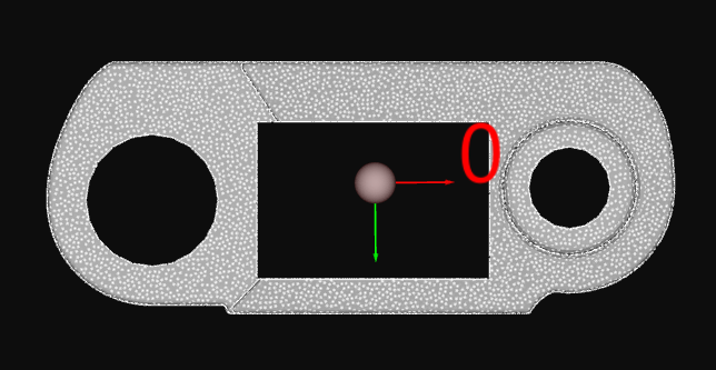
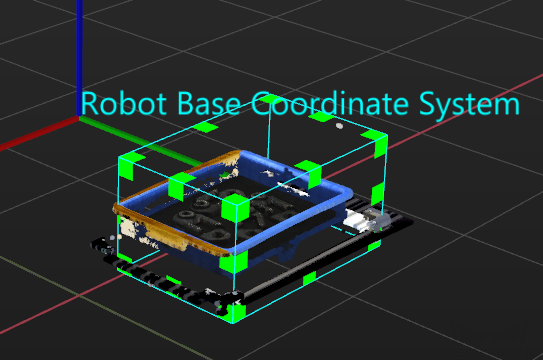
In visualized interface, set the region for recognition (3D ROI). Press and hold the Ctrl key, select the vertices of the 3D ROI, and drag the 3D ROI to the proper size. The following figure displays the set 3D ROI.
-
Save the region for recognition.
Click Save and apply to save the region for recognition.
Now, you have finished the preprocessing procedure. Click Next at the bottom of the 3D workpiece recognition visualized configurator to enter the recognition procedure.
Recognize workpieces
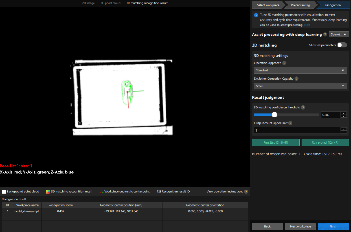
In this procedure, you can adjust the 3D matching related parameters in a visualized manner, and output the workpieces’ poses.
The following figure displays the Recognition interface.
-
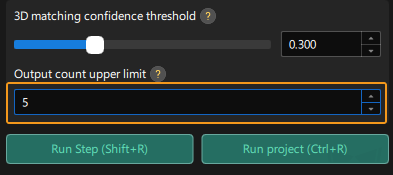
Since the robot needs to pick and place one workpiece based on the returned vision result in this tutorial, change the Output count upper limit parameter to 1 for this project.
-
View the visualized output result
Click the Run Step (Shift+R) button.

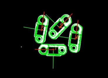
You can view the visualized output result in the visualized area. As the figure below, the pose of one workpiece is output.
-
Save the configuration.
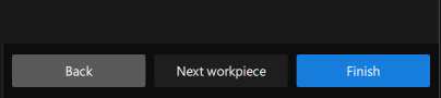
Click the Finish button at the bottom of the 3D workpiece recognition visualized configurator.
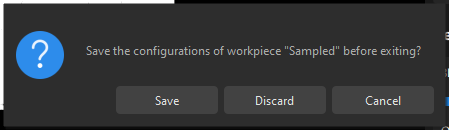
Click Save in the pop-up window.
Now, you have recognized the workpiece and calculated its pick point.
Adjust Poses V2
The pick points output by the 3D Workpiece Recognition Step is in the camera reference frame. To facilitate robot picking, you need to adjust the workpieces’ poses to transform them from the camera reference frame to the robot reference frame.
-
Open the pose adjustment tool.
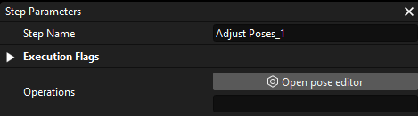
Select the Adjust Poses V2 Step, and click the Open the editor button in the Step Parameters panel.
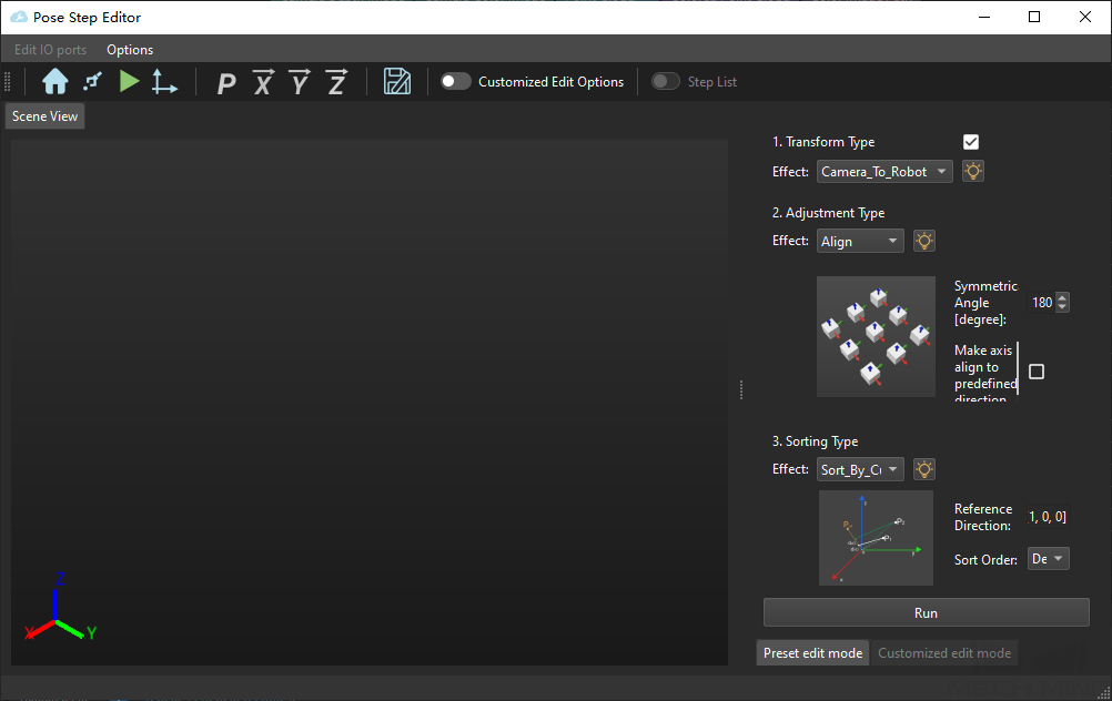
The interface of the pose adjustment tool is shown below.
-
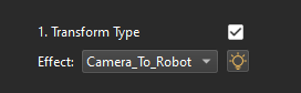
Adjust the reference frame.
In the upper-right corner of the pose adjustment tool, under Reference Frame Settings, check the Convert Poses to the Robot Reference Frame option.
-
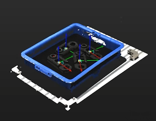
View the reference frame transformation result.
Click the Next button in the lower-right corner of the pose adjustment tool.
You can see the transformed pick points in the Scene Viewer of the pose editor.
-
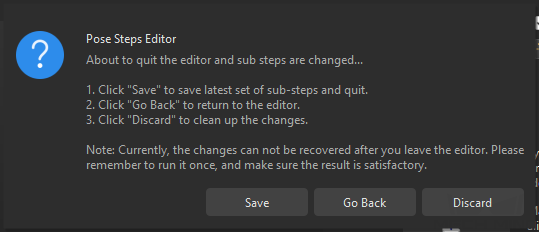
Save the configuration.
Close the pose editor, and click Save in the pop-up window.
Now, the reference frame of the pick points has been transformed.