Pick and Place
After having obtained the poses of workpieces using a Mech-Vision case project, you can then build a workflow for the Mech-Viz project to guide the robot to repeatedly pick and place workpieces.
| In this tutorial, the model file of the end tool in the OBJ format is required for collision detection. You can download it by clicking here. |
Video tutorial: Perform Picking
|
The following figure shows the workflow to build.

Configure the Robot and Scene
To avoid collision with surrounding objects during robot picking and placing, you should add the tool model, scene model, and bin models to the project for collision detection.
Import and Configure the Tool Model
|
Tool refers to the device mounted on the robot end that performs processing/picking jobs. |
The end tool should be imported and configured so that its model can be displayed in the 3D simulation space and used for collision detection.
Import the Tool Model
-
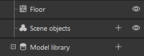
Click + in .
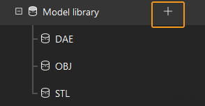
Project resources refer to various fundamental resources used in the project, including the robot, tools, workobjects, and scene objects.
-
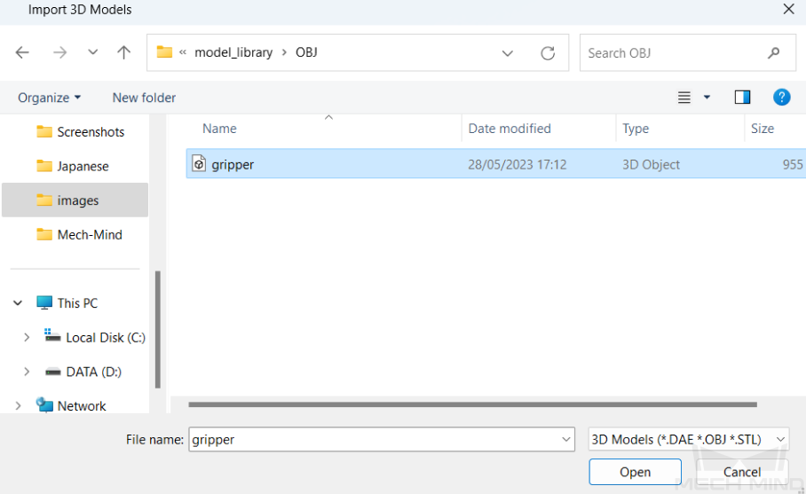
In the prompted window, select the collision model file in OBJ format, and then click Open.
-
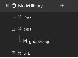
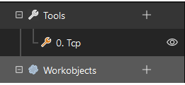
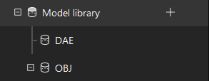
After the model is imported, you can see the imported model in the model library.
Configure the Tool
-
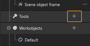
Click + in .
-
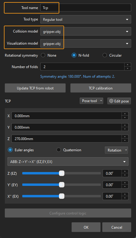
In the prompted window, enter the tool name, select the imported tool model as the collision model and visualization model, and then click OK.
-
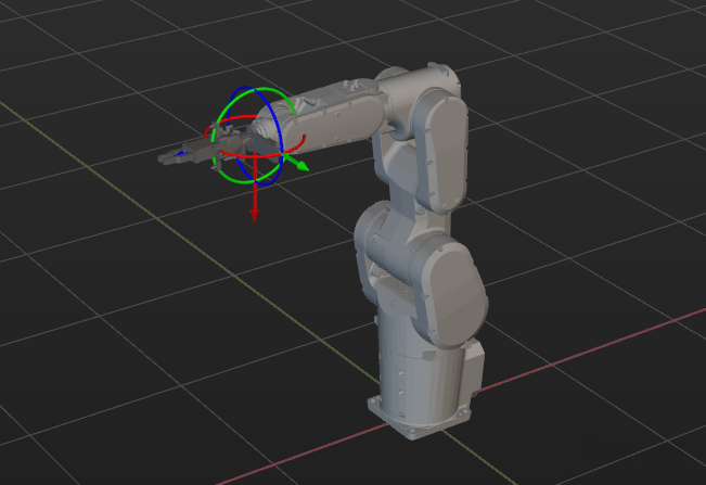
After the tool is configured, you can view the configured tool in the 3D simulation space, as shown below.
Adjust the Tool
As shown above, the position of the Tool Center Point (TCP) in relation to the robot is obviously wrong. So, you should adjust the position of the TCP so that it is at the tip of the tool.
-
Double-click the tool model in the model library.
-
In the prompted windows, adjust the settings as shown below.

-
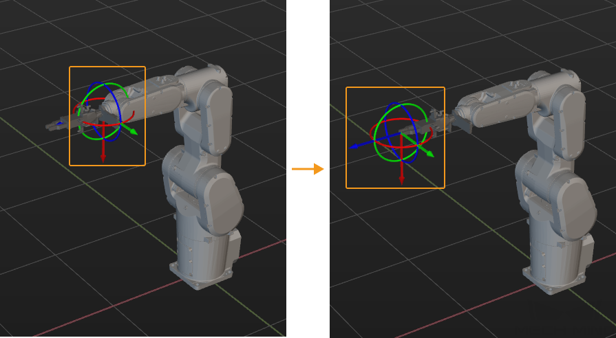
The poses of the tool before and after fitting are shown below.
Import and Configure the Scene Model
Scene objects are imported and configured to make the scene in the software closer to the real scenario, which facilitates the planning of the robot motion path.
Import the Scene Model
-
Click + in .
-
In the prompted window, select the scene object model file, and then click Open.
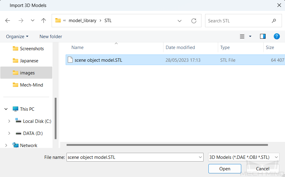
-
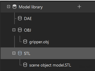
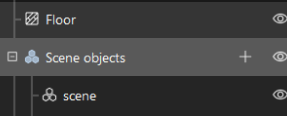
After the model is imported, you can see the imported model in the model library.
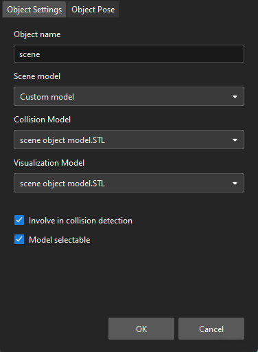
Configure the Scene Model
-
Click + in .
-
In the prompted window, enter the object name, select “Custom model” as the “Scene model”, select the imported scene object model as the collision model and visualization model, and then click OK.
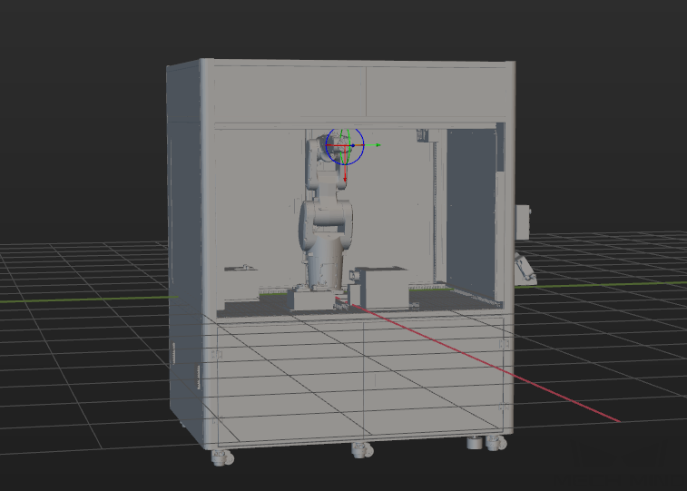
-
After configuration, the scene object is displayed in the 3D simulation space.
Add and Configure the Bin Models
-
Add the picking bin model.
Click + in .
In the prompted window, set the Object name to picking bin, and the Scene model to Bin. Then set the “Object dimensions” parameter according to the measured size of the real bin, and then click OK.
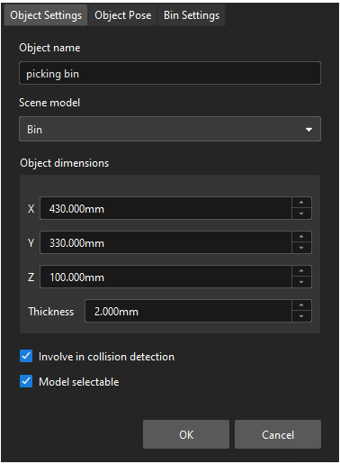
After configuration, the “picking bin” model is displayed in the 3D simulation space.
-
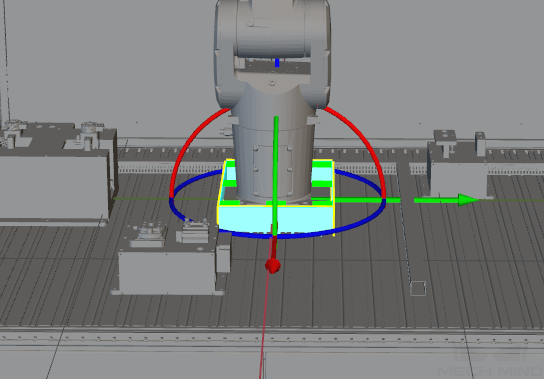
Adjust the picking bin model.
To determine the position of the real bin, you can run the Mech-Vision project to send the point cloud of the real bin to Mech-Viz. Then, you can adjust the pose of the “picking bin” based on the point cloud position of the real bin.
Press the Ctrl key and press the left mouse button to drag the axis of the picking bin model to coincide with the point cloud position of the real bin. The position of the picking bin model after adjustment is shown below.
-
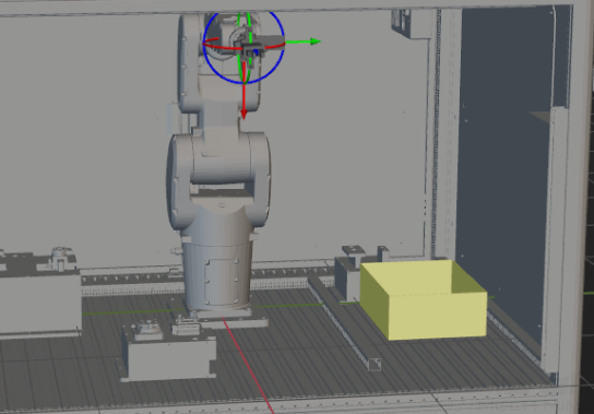
Add and adjust the placing bin model.
Use the same method to add and adjust the placing bin model, as shown below.

So far, you have added all the resources required by the Mech-Viz project.
Create a Workflow
Now that you have configured the models, you can start creating a workflow. Drag a step from the step library to the graphical programming workspace, set the parameters of the Steps, and connect Steps to achieve preset program functions.
|
Introduction to the Project Workflow
The created workflow is shown below. This workflow is for reference only and should be adjusted according to the on-site situation.
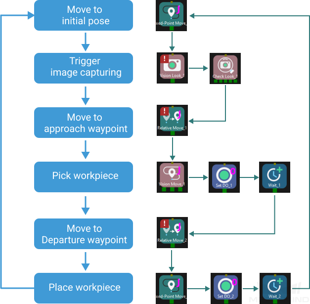
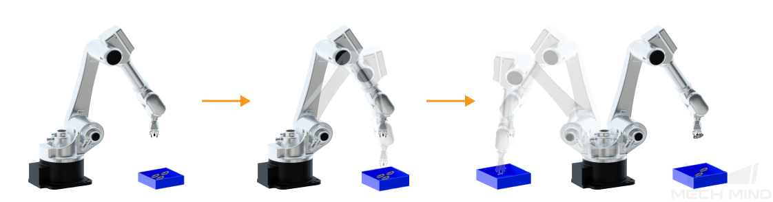
The created workflow can achieve the picking and placing as shown below.
Define the “Home Position”
The home position is the starting point of the robot movement and should also be a safe position. At this point, the robot should be away from the objects to pick and the surrounding devices, and should not block the camera’s FOV.
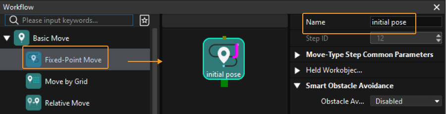
After the robot arrives at the self-defined home position, select Fixed-Point Move in the Step Library, and drag it to the graphical programming workspace, rename it as “initial pose”. Then click Sync Robot on the toolbar to record the current pose of the robot for this Step.
Trigger the Camera to Capture Images
Step |
Vision Look |
Description |
Start the Mech-Vision project to obtain the vision recognition result. |
Operation |
Find the Vision Look Step in the Step Library, and drag it to the graphical programming workspace. |
Parameter Settings |
Select General_Workpiece_Recognition from the Vision Name drop-down list. |
Illustration |
|

After the “Vision Look” Step, add the Check Look Step to check whether there is any vision result.
Step |
Check Look |
Description |
Check whether there is any vision result. |
Operation |
Find the “Check Look” Step in the Step Library, and drag it to the graphical programming workspace. |
Parameter Settings |
Keep the default parameter settings. |
Move the Robot to the Approach Waypoint
After obtaining the vision recognition result, you can then use the Relative Move step to move the robot to the approach waypoint.
Step |
Relative Move |
Description |
The robot moves according to the vision recognition result. |
Operation |
Find the Relative Move Step in the Step Library, drag it to the graphical programming workspace, and rename it as “Approach waypoint”. |
Parameter Settings |
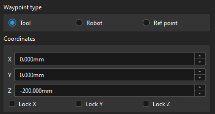
In the Relative Move Reference Point, select Next waypoint in the drop-down list box of Reference Point; set Waypoint type to Tool, and set Z coordinate to -200 mm. |
Illustration |
|

Pick the Workpiece
After the robot has arrived at the approach waypoint, you can control the robot the pick workpieces. The picking process can be divided into two steps.
-
Step 1: Use the Vision Move Step to control the robot to reach the picking waypoint of the workpiece.
-
Step 2: Use the Set DO Step to control the robot to expand the gripper to pick the workpiece.
See the following for details.
Step |
Vision Move |
Description |
The robot moves according to the vision recognition result. |
Operation |
Find the Vision Move Step in the Step Library, and drag it to the graphical programming workspace. |
Parameter Settings |
Select General_Workpiece_Recognition from the Vision Name drop-down list. |
Illustration |
|
Step |
Set DO |
Description |
Control the robot to expand the gripper to pick the workpiece. |
Operation |
Find the Set DO Step in the Step Library, drag it to the graphical programming workspace, and rename it as “expand the gripper”. |
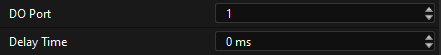
Parameter Settings |
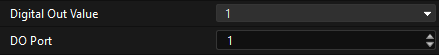
Set the Digital Out Value and DO Port parameters to 1. |
Illustration |
|
Since it takes time for the gripper to expand, you should add the Wait Step to avoid empty picking by the robot.
Step |
Wait |
Description |
Avoid an empty pick by the robot. |
Operation |
Find the Wait Step in the Step Library, drag it to the graphical programming workspace, and rename it as “Wait for firm gripping”. |
Parameter Settings |
Set the Wait Time parameter to 1000ms. |
Illustration |
|

Move the Robot to the Departure Waypoint
After the robot picks the workpiece, you should add the Relative Move Step to control the robot to arrive at the departure waypoint.
Step |
Relative Move |
Description |
The robot moves according to the vision recognition result. |
Operation |
Find the Relative Move Step in the Step Library, drag it to the graphical programming workspace, and rename it as “Departure waypoint”. |
Parameter Settings |
In the Relative Move Reference Point. Select Next waypoint in the drop-down list box of Reference point; set Waypoint type to Tool, and set Z coordinate to -200 mm. |
Illustration |
|
Place the Workpiece
After the robot picks the workpiece, the robot needs to place the workpiece into the placing bin. The placing process can be divided into two steps.
-
Step 1: Use the Fixed-Point Move Step to control the robot to arrive at the position of the placing bin.
-
Step 2: Use the Set DO Step to control the robot to close the gripper to place the workpiece.
See the following for details.
Step |
Fixed-Point Move |
Description |
Control the robot to arrive at the position of the placing bin. |
Operation |
Find the Fixed-Point Move Step in the Step Library, drag it to the graphical programming workspace, and rename it as “Placing waypoint”. |
Parameter Settings |
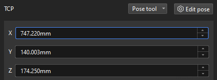
Set a suitable TCP as the placing waypoint. |
Illustration |
|
Step |
Set DO |
Description |
Control the robot to close the gripper to place the workpiece. |
Operation |
Find the Set DO Step in the Step Library, drag it to the graphical programming workspace, and rename it as “retract the gripper”. |
Parameter Settings |
Set the Digital Out Value parameter to 0 and the DO Port parameter to 1. |
Illustration |
|
Since it takes time for the gripper to close, you should add the Wait Step to avoid that the robot cannot place the workpiece.
Step |
Wait |
Description |
Avoid the failure of placing the workpiece by the robot. |
Operation |
Find the Wait Step in the Step Library, drag it to the graphical programming workspace, and rename it as “Wait for release”. |
Parameter Settings |
Set the Wait Time parameter to 1000ms. |
Illustration |
|
Simulate and Run the Project
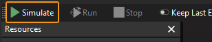
-
After all the Steps are connected properly, click the Simulate button on the toolbar to simulate the Mech-Viz project.
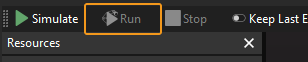
-
If the project runs as expected in simulation, click the Run button on the Mech-Viz toolbar to run the project with the real robot.
|
It is recommended that the robot should move at a low speed and that you pay attention to the robot motion trajectory. In an emergency, press the emergency stop key on the teach pendant. |
Till now, you have successfully deployed a simple 3D vision-guided robotic application of picking small metal parts in the Master-Control communication mode.