Vision System Hardware Setup
In this tutorial, you will learn how to build the Mech-Mind Vision System.
To construct the Mech-Mind vision system, you need to follow these steps: Check package contents → Install the hardware → Connect the network → Upgrade software (optional) → Confirm that the vision system can capture images normally.
Video Tutorial: Vision System Hardware Setup
|
Check Contents of the Package
-
After receiving the package from the camera, please make sure that the package is intact.
-
Check the contents against the “packing list” in the package to ensure that no devices or accessories are missing or damaged.
The following figure shows the items and accessories included in the package for reference only. Please take the “packing list” in the actual package as the final.
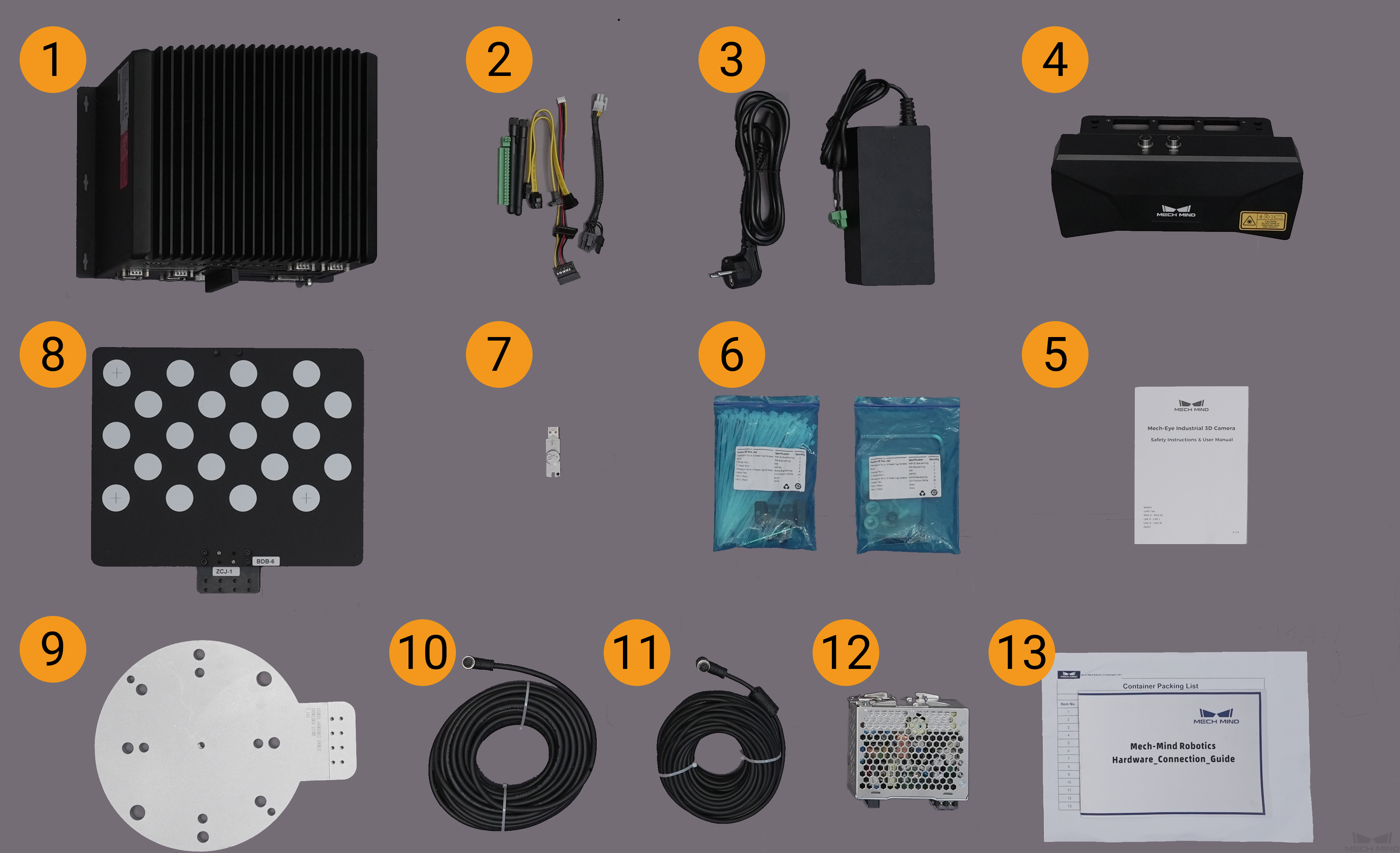
| No. | Category | Name | Function |
|---|---|---|---|
1 |
IPC and accessories |
Mech-Mind IPC STD |
Provides running environment for Mech-Mind software |
2 |
IPC accessories |
IPC accessories such as mounting brackets, external WiFi antennas, securing screws |
|
3 |
IPC power cable |
Supplies power to IPC |
|
4 |
Camera and accessories |
Mech-Eye Industrial 3D Camera |
Capture Images |
5 |
User manual |
Mech-Eye Industrial 3D Camera User Manuals |
|
6 |
Camera accessory box |
Mount the Camera |
|
7 |
Project accessories |
License dongle |
Licensed Software |
8 |
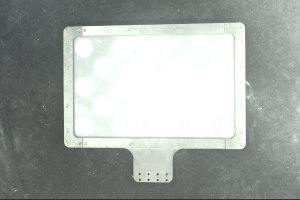
Calibration board |
Calibration Camera |
|
9 |
Flange adapter |
Connects the calibration board to the robot flange |
|
10 |
Camera DC power cable (standard: 20 meters) |
Connects the camera and the DIN rail power supply; Longer power cables are an option |
|
11 |
Camera Ethernet cable (standard: 20 meters) |
Connects the camera and the IPC; longer camera Ethernet cables are an option |
|
12 |
DIN rail power supply (standard) |
Supplies power to Mech-Eye Industrial 3D Camera; the camera power adaptor is an option |
|
13 |
Packing list |
Lists all the devices and accessories in the package |
|
|
Contact Mech-Mind if any items are missing or damaged. |
Prepare Other Materials
In this tutorial, besides the items in the package, you still need to prepare the materials shown in the following table by yourself.
| Item | Function |
|---|---|
Monitor |
Provides display for the IPC |
HDMI cable |
Connects the monitor and the IPC |
RJ45 Ethernet cable |
Connects the IPC and the robot controller |
| In this tutorial, the IPC and robot controller are directly connected through an RJ45-to-RJ45 Ethernet cable, and the IPC and the camera are directly connected through the camera Ethernet cable. Alternatively, you can use a router to connect the IPC and the robot controller, and the IPC and the camera, which is not covered in this topic. |
Install Hardware
Mount the Camera
|
In this tutorial, the camera is mounted on the camera mounting frame (that is the eye to hand (ETH) mounting mode). In addition, the camera can also be mounted onto the end terminal of the robot (that is the eye in hand (EIH) mounting mode). |
-
Get the camera mounting bolts and wrench from the camera accessory box.
-
Tighten the two bolts with the wrench as shown below.

-
Please remove the lens protection film after mounting the camera.
-
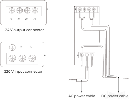
Power the camera with the DIN rail power supply.
-
Connect the DC power cable:
-
Connect +V wire to +V connectors of the 24 V output connectors;
-
Connect -V wire to -V connectors of the 24 V output connectors;
-
Connect the PE wire to the 220 V input connector
 .
.
-
-
-
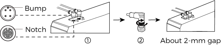
Install the Ethernet cable of the camera.
Make sure the bump of the M12 connector and the notch of the ETH port, and tighten the nut after plugging in the cable.
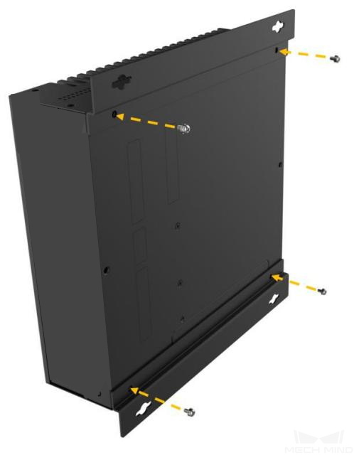
Mount the IPC with Mounting Frames
Follow these steps to secure the embedded device to a wall or other surface with two mounting brackets.
-
Flip this device.
-
Align the mounting screw holes on both sides of the bracket with the corresponding mounting screw holes on the bottom.
-
Secure the device and bracket by inserting retaining screws into the brackets separately.
-
Make holes in the predetermined mounting surfaces.
-
Align the mounting holes on both sides of the mounting frame with the holes drilled on the predetermined mounting surface.
-
Insert and tighten the 4 retaining screws to secure the device to the target mounting surface.
-
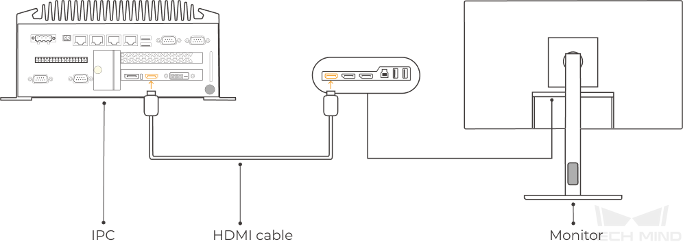
Connect the IPC and the monitor with the HDMI cable.
Plug one end of the HDMI cable into the HDMI port of the monitor, and the other end into the HDMI port of the IPC, as shown below.
-
Connect the IPC to the power supply unit with the power adaptor.
Plug the power cable of the power adaptor into the power connector of the IPC. Connect the adaptor to the power supply on the other end.
-
Insert the license dongle.
Plug the license dongle into a USB port of the IPC.
-
After the IPC is connected to the power supply, switch on the IPC.
-
If the IPC is started normally, the power indicator should be solid on.
-
If the IPC cannot be started, contact Mech-MindTechnical Support.
-
Connect the Network
In this section, you will learn how to connect the network between the IPC and the camera, and between the IPC and the robot.
In the following sections, the following IP addresses will be used for network settings. Please adjust the network settings according to your actual network environment.
| Device | IP Address | |
|---|---|---|
IPC |
Ethernet port connecting to the camera |
192.168.100.10 |
Ethernet port connecting to the robot controller |
192.168.200.10 |
|
Camera |
192.168.100.20 |
|
Robot |
192.168.200.20 (already set on the robot) |
|
Connect the IPC and the Camera, and the IPC and the Robot Controller
-
Plug the other end of the Ethernet cable connected to the camera into an Ethernet port of the IPC.
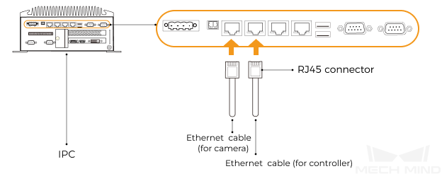
-
Use an RJ45-to-RJ45 Ethernet cable to plug one end into the Ethernet port of the robot controller and the other end into an Ethernet port of the IPC.
Set the IP Addresses on the IPC
-
Select on the IPC. The Network Connections page will be displayed.
-
Right-click the Ethernet port connected to the camera, and select Rename to rename the Ethernet port, such as “To_camera”.
-
Right-click the Ethernet port connected to the camera, and select Properties to enter the Ethernet Properties page.
-
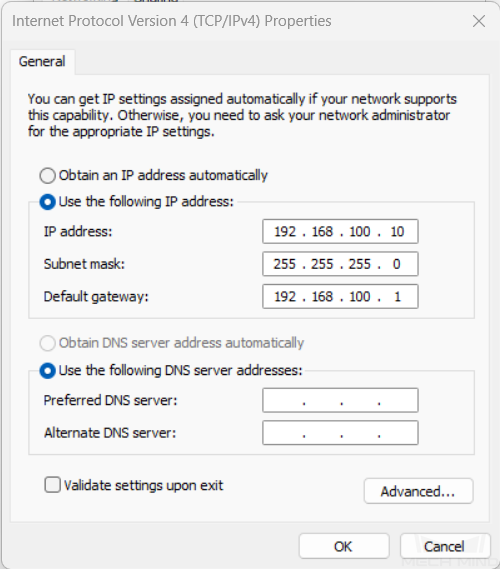
Select the Internet Protocol Version 4 (TCP/IPv4) checkbox, and then click the Property button to enter the Internet Protocol Version 4 (TCP/IPv4) Properties page.
-
Select the Use the following IP address radio button, set the IP address parameter to “192.168.100.10”, Subnet mask to “255.255.255.0”, and Default gateway to “192.168.100.1”, and then click the OK button.
-
Repeat steps 2 to 5 to rename the Ethernet port connected to the robot controller (for example, “To_robot”), and set the IP address for this Ethernet port. For example, set the IP address of this Ethernet port to “192.168.200.10”.
The IP address of the robot and that of the IPC Ethernet port connected to the robot controller must be on the same subnet.
Set the Camera IP Address
-
Double-click
 on the desktop of the IPC to open and run Mech-Eye Viewer.
 -
Select the camera in the camera list, and hover the cursor on the camera. Click
 to open the Config Camera Network dialog box.
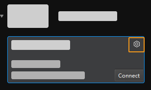
If the camera cannot be found or connected, please refer to Camera Troubleshooting.
-
In the Camera area, select the Set as Static IP radio button, set IP Address Class to “Class C 192.168.x.x”, IP Address to 192.168.100.20, and Subnet Mask to “255.255.255.0” and then click Apply.
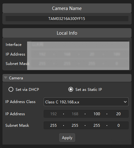
|
The IP address of the camera and that of the IPC Ethernet port connected to the camera must be on the same subnet. |
Test the Network Connectivity
-
Press Win + R to open the Run dialog box.
-
Type
cmdin the Run dialog box, and then click OK. -
Type ping XXX.XXX.XX.XX in the command prompt window, and press Enter to run the command.
Replace XXX.XXX.XX.XX with the actual IP address of the camera/robot.
If the network connectivity is normal, you should receive the following response:
Pinging XXX.XXX.XX.XX with 32 bytes of data:
Reply from XXX.XXX.XX.XX: bytes=32 time<1ms TTL=128
Reply from XXX.XXX.XX.XX: bytes=32 time<1ms TTL=128
Reply from XXX.XXX.XX.XX: bytes=32 time<1ms TTL=128
Reply from XXX.XXX.XX.XX: bytes=32 time<1ms TTL=128
Upgrade the Software (Optional)
The IPC purchased from Mech-Mind already has the latest version of Mech-Mind software installed.
Please check if all software on the IPC is running with the latest version. If so, skip this section; if not, follow the sections below to update the software to the latest versions.
Confirm the Quality of Captured Images
After verifying the network connectivity between the IPC and the camera and robot, and confirming that the software is the latest version, please confirm that the vision system can capture images normally and that the image quality meets the requirements:
-
Place workpieces at the center of the camera’s field of view (FOV), and make sure that the workpieces on the edge and top are all within the FOV.
-
Open and start Mech-Eye Viewer by double-clicking
on the desktop of the IPC. -
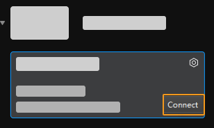
Select the camera in the camera list and click Connect.
-
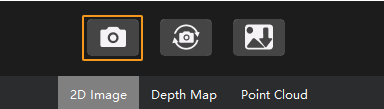
After the camera is connected, click Capture once.
-
Make sure that the captured images meet the following standards.
-
2D image: the captured 2D image should not be overexposed or underexposed; the surface features of the target object should be clearly visible.
Normal Overexposed Underexposed 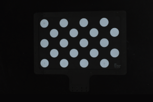

-
Depth map and point cloud: in the depth map and point cloud, the data corresponding to the target object should be complete.
Point cloud complete Point cloud incomplete Point cloud incomplete 
-
|
If the captured images do not meet the requirements, please use Mech-Eye Viewer to adjust camera parameters. |
Up to now, you have learned how to build the vision system.