Pick and Place
In this tutorial, you will learn how to write a robot program to build a simple pick-and-place process.
In this tutorial, the robot program provides the following functions:
-
When the program is run once, the Mech-Vision project is run once.
-
Every time the Mech-Vision project is run, one vision point (TCP) can be obtained by the robot.
-
The robot picks and places a workpiece based on the returned vision result and the programmed pick-and-place path.
Video Tutorial: Configuration and Running
|
Introduction to Communication
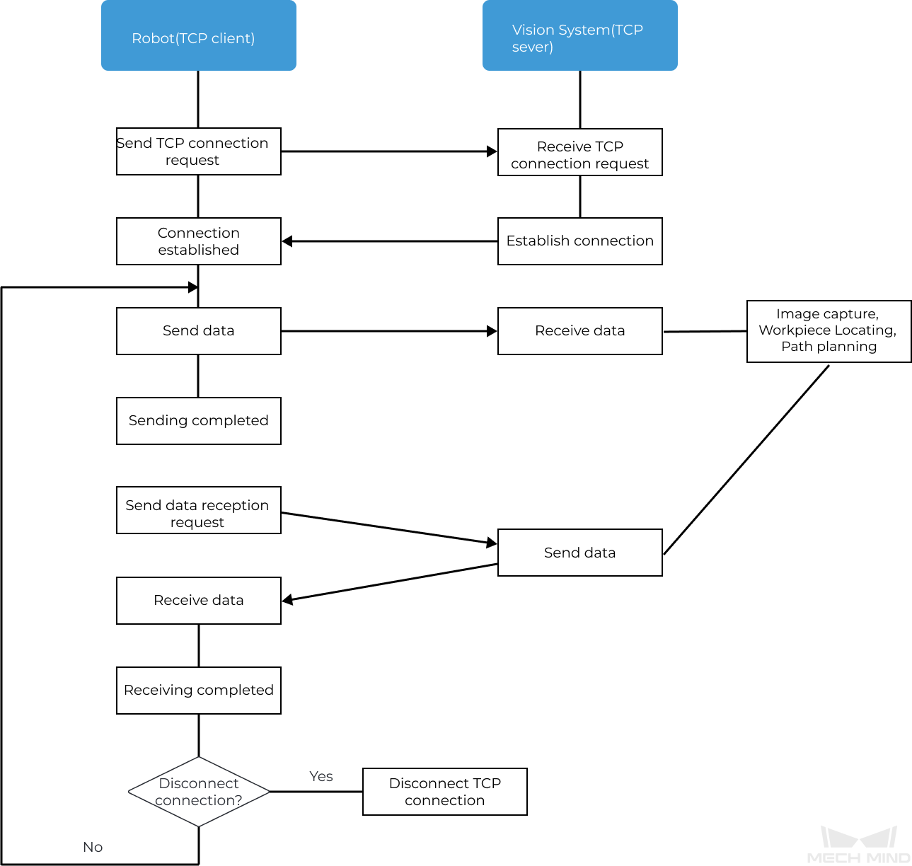
This section describes the fundamental principles of communication between Yaskawa robots and the Mech-Mind Vision System briefly.
Yaskawa robots and the Mech-Mind Vision System use the Transmission Control Protocol (TCP) Socket protocol (in ASCII data format) for the Standard Interface communication. During the communication, the robot acts as a TCP client while the vision system acts as a TCP server. The process of communication between a robot and the vision system is shown below.
Introduction to Programming
This section provides some basic knowledge that you should know to write a pick-and-place program for Yaskawa robots.
The purpose of writing a robotic pick-and-place program is to achieve Standard Interface communication between a robot and the vision system, as well as enabling the robot to perform pick-and-place tasks under vision guidance. This program contains a range of functions such as TCP connection establishment/disconnection, data transfer, robot motion control, digital output (DO) control, etc. When writing a pick-and-place program, you need to use two types of commands: Yaskawa robot commands and Standard Interface commands.
Yaskawa Robot Commands
YASKAWA robot commands refer to the commands supported by the YASKAWA INFORM robot language, including input/output commands, control commands, math commands, motion commands, shift commands, and additional commands. Section Yaskawa Robot Command Reference will briefly introduce the commands used for writing a pick-and-place program.
Standard Interface Commands
Standard Interface commands refer to the commands supported by the Standard Interface program loaded to the YASKAWA robot. These commands are used for Standard Interface communication with the vision system and include commands related to TCP socket communication, data exchange, and other functions. For the Standard Interface commands supported by YASKAWA robots, please refer to YASKAWA Standard Interface Functions.
The Standard Interface commands supported by Yaskawa robots are encapsulated in the frontend programs (Jobs) loaded to the robot. After loading frontend programs to the robot, you can use the YASKAWA command CALL to call a Standard Interface command encapsulated in a frontend program, for example: CALL JOB:MM_OPEN_SOCKET.
How to Write a Pick-and-Place Program?
The easiest way to write a pick-and-place program is to modify an existing example program and debug it.
To facilitate the quick preparation of a pick-and-place program in collaboration with the Mech-Mind Vision System, Mech-Mind provides three pick-and-place example programs. This tutorial will modify the first example program and debug it. This example program enables a simple pick-and-place, where one vision point is obtained at a time from the vision system (only Mech-Vision used), and then picks and places the target object.
The code for this example program is displayed below:
NOP
'*****************************
'FUNCTION:simple pick and place
'with Mech-Vision
'mechmind, 2022-5-27
'*****************************
'clear I50 to I69
CLEAR I050 20
'Initialize p variables
SUB P070 P070
SUB P071 P071
'set  200mm to Z
SETE P070 (3) 200000
'move to the home position
MOVJ C00000 VJ=80.00
'move to the camera position
MOVJ C00001 VJ=80.00 PL=0
'set ip address of IPC
CALL JOB:MM_INIT_SOCKET ARGF"192.168.170.22;50000;1"
TIMER T=0.20
CALL JOB:MM_OPEN_SOCKET
'set vision recipe
CALL JOB:MM_SET_MODEL ARGF"1;1"
'Run vision project
CALL JOB:MM_START_VIS ARGF"1;0;2"
'get result from Vis
CALL JOB:MM_GET_VISDATA ARGF"1;51;52"
PAUSE IF I052<>1100
'set the first pos to P071;
'set lables to I61;
'set speed to I62;
CALL JOB:MM_GET_POSE ARGF"1;71;61;62"
SFTON P070
MOVJ P071 VJ=50.00
SFTOF
MOVL P071 V=80.0 PL=0
'enable gripper
DOUT OT#(1) ON
SFTON P070
MOVJ P071 VJ=50.00
SFTOF
MOVJ C00002 VJ=80.00
'drop point
MOVJ C00003 VJ=80.00 PL=0
'release gripper
DOUT OT#(1) OFF
CALL JOB:MM_CLOSE_SOCKET
END
The pick-and-place process built by the preceding example program is shown in the figure below.
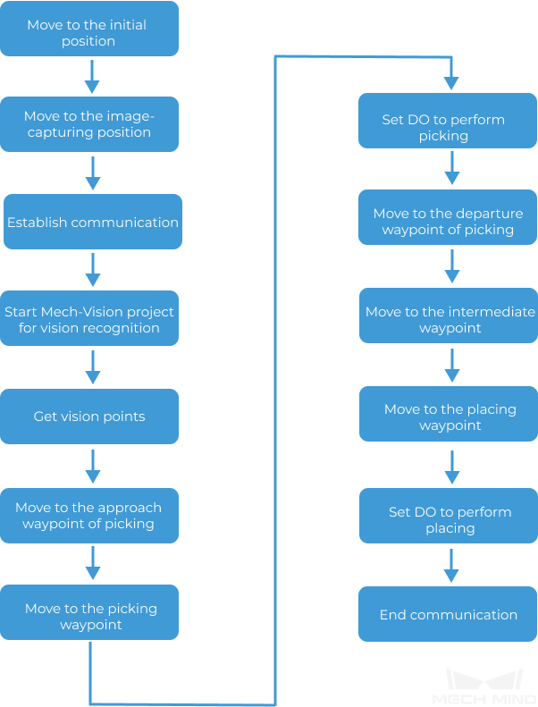
The following table describes each step in the pick-and-place process and the required modification.
| Step | Code | Description | ||
|---|---|---|---|---|
Initialize variables |
NOP 'clear I50 to I69 CLEAR I050 20 'Initialize p variables SUB P070 P070 SUB P071 P071 'set 200mm to Z SETE P070 (3) 200000 |
This step initializes integer variables and position variables used in the program. Usually, no modification of the corresponding code block is required. |
||
Move to the Initial Position |
'move to the home position MOVJ C00000 VJ=80.00 |
This step moves the robot TCP to the initial position in the TEACH mode. The initial position is the starting point of the robot motion, and it should also be a safe position. At this position, the robot should be away from the objects to pick and the surrounding devices, and should not block the camera’s field of view (FOV).
|
||
Move to the image-capturing position |
'move to the camera position MOVJ C00001 VJ=80.00 PL=0 |
This step moves the robot TCP to the image-capturing position that has been taught. The image-capturing position refers to the position where the robot captures images. At this position, the robot arm should not block the camera’s FOV.
|
||
Establish Communication |
'set ip address of IPC CALL JOB:MM_INIT_SOCKET ARGF"192.168.170.22;50000;1" TIMER T=0.20 CALL JOB:MM_OPEN_SOCKET |
This step initializes the parameters involved in communication and establishes TCP Socket communication with the vision system.
|
||
Start Mech-Vision Project for Vision Recognition |
'set vision recipe CALL JOB:MM_SET_MODEL ARGF"1;1" 'Run vision project CALL JOB:MM_START_VIS ARGF"1;0;2" |
In this step, you need to switch the Mech-Vision parameter recipe (necessary for more than one workpiece), and then start Mech-Vision project to recognize the picking poses of workpieces. In this tutorial, only one type of workpiece is involved, so there is no need to switch the parameter recipe.
|
||
Get Vision Points |
'get result from Vis CALL JOB:MM_GET_VISDATA ARGF"1;51;52" PAUSE IF I052<>1100 'set the first pos to P071; 'set lables to I61; 'set speed to I62; CALL JOB:MM_GET_POSE ARGF"1;71;61;62" |
This step obtains the vision point from Mech-Vision and saves the TCP, its corresponding label value, and speed value in variables.
|
||
Move to the Approach Waypoint of Picking |
SFTON P070 MOVJ P071 VJ=50.00 SFTOF |
This step moves the robot TCP to the approach waypoint of picking, which prevents the robot from colliding with scene objects (such as bins) when moving directly from the image-capturing position to the picking waypoint. The sample code moves the robot TCP to 200 mm above the picking waypoint (P071) by default (the approach waypoint of picking). If the distance between the approach waypoint of picking and the picking waypoint is too short, you can modify the Z-axis value of variable P070. 'set 200mm to Z SETE P070 (3) 200000 |
||
Move to the Picking Waypoint |
MOVL P071 V=80.0 PL=0 |
This step moves the robot TCP to the picking waypoint (P071). The example moves the robot TCP from the approach waypoint of picking to the picking waypoint in linear motion by default. You can use the code snippet in the sample directly without modification. |
||
Set DO to Perform Picking |
'enable gripper DOUT OT#(1) ON |
This step expands the claw gripper to pick workpieces. The claw gripper used in this tutorial will expand to pick workpieces when the general output signal with ID 2 is connected. Therefore, this step requires modifying the general output signal ID to 2. In real application scenarios, please modify the general output signal ID according to the actual situation. |
||
Move to the Departure Waypoint of Picking |
SFTON P070 MOVJ P071 VJ=50.00 SFTOF |
This step moves the robot TCP to the departure waypoint of picking, which prevents the robot from colliding with scene objects (such as bins) after picking the workpieces. The example program moves the robot TCP to 200 mm above the picking waypoint (P071) by default (the departure waypoint of picking). If the distance between the departure waypoint of picking and the picking waypoint is too short, you can modify the Z-axis value of variable P070. 'set 200mm to Z SETE P070 (3) 200000
|
||
Move to the Intermediate Waypoint |
MOVJ C00002 VJ=80.00 |
This step moves the robot TCP to the intermediate waypoint in the TEACH mode, which prevents the robot from colliding with scene objects. Teach the intermediate waypoint in this step. Add more intermediate waypoints according to your needs. |
||
Move to the Placing Waypoint |
'drop point MOVJ C00003 VJ=80.00 PL=0 |
This step moves the robot TCP to the placing waypoint in the TEACH mode. Teach the placing waypoint in this step. |
||
Set DO to Perform Placing |
'release gripper DOUT OT#(1) OFF |
This step opens the claw gripper to place workpieces. The claw gripper used in this tutorial will open to place workpieces when the general output signal with ID 1 is connected. Therefore, this step requires modifying the state of the general output with signal ID 1 to ON. In real application scenarios, please modify the general output signal ID and state according to the actual situation. |
||
End Communication |
CALL JOB:MM_CLOSE_SOCKET END |
This step ends TCP Socket communication. This line of code does not need to be modified. |
| For more information about the example program, please refer to Explanations to the Example Program. |
Modify and Debug the Example Program
| The robot pose in this example program is TCP. Before modifying and debugging the example program, please switch the tool number to the gripper No. (for example, 01) and complete the TCP settings of the tool. |
Open the Example Program
To modify and debug the robot pick-and-place example program, you need to open the example program first:
-
In the Online mode, select on the Main Menu to enter the JOB LIST interface.
-
Select the mm_sample program and press the Select key to open it.
| The code snippet at the beginning of the example program initializes variables and usually does not need to be modified. |
Move to the Initial Position
This step moves the robot TCP to the initial position in the TEACH mode. Teach the initial position for the robot here.
This step requires modifying the code snippet below.
'move to the home position MOVJ C00000 VJ=80.00
Perform the following operations to teach the initial position for the robot:
-
Twist the mode key on teach pendant to
TEACHto enter the TEACH mode. -
Manually move the robot to the initial position so that the program can start executing from the beginning.
-
Press the ▼ key on the teach pendant to select the line "MOVJ C00000 VJ=80.00", press the Modify key, and then press the Enter key to confirm changing the initial position to the robot’s current TCP.
"VJ=80.00" means the joint speed is 80%. This parameter can remain unchanged.
Move to the Image-capturing Position
This step moves the robot TCP to the image-capturing position that has been taught. Teach the image-capturing position for the robot here.
This step requires modifying the code snippet below.
'move to the camera position MOVJ C00001 VJ=80.00 PL=0
Perform the following operations to teach the image-capturing position for the robot:
-
In the TEACH mode, manually move the robot to the image-capturing position.
-
Press the ▼ key on the teach pendant to select the line "MOVJ C00001 VJ=80.00 PL=0", press the Modify key, and then press the Enter key to confirm changing the image-capturing position to the robot’s current TCP.
"VJ=80.00" means the joint speed is 80%; "PL=0" means the position level is 0. These two parameters can remain unchanged. The position level is used to determine how close the robot is to the teaching position when it is in that position. The value range is from 0 to 8, with smaller values indicating closer proximity.
Establish Communication
This step begins the communication between the robot and the vision system. In this step, you need to modify the corresponding parameters (the IP address and port of the IPC) of the “Initialize Communication” command (MM_INIT_SOCKET).
The code snippet that needs to be modified is as follows.
'set ip address of IPC CALL JOB:MM_INIT_SOCKET ARGF"192.168.170.22;50000;1" TIMER T=0.20 CALL JOB:MM_OPEN_SOCKET
Perform the following operations to modify the parameters of the “Initialize Communication” command:
-
In the TEACH mode, press the ▼ key on the teach pendant to select the line “CALL JOB:MM_INIT_SOCKET ("192.168.170.22;50000;1")” and press the Select key.
-
Use the soft keyboard on the teach pendant screen to modify "192.168.170.22" and "50000" to the IP address and port of the IPC respectively, and then press the Confirm key on the screen to confirm the modification.
Start Mech-Vision Project for Vision Recognition
This step starts the Mech-Vision project to perform vision recognition and output vision results.
In this step, you need to modify the parameters of the “Trigger Mech-Vision Project” command. In this tutorial, only one type of workpiece is involved, so you need to comment out the “Switch Mech-Vision Recipe” command.
The code snippet that needs to be modified is as follows.
CALL JOB:MM_SET_MODEL ARGF"1;1" 'Run vision project CALL JOB:MM_START_VIS ARGF"1;0;2"
Perform the following operations to comment out the “Switch Mech-Vision Recipe” command and then modify the parameters of the “Trigger Mech-Vision Project” command:
-
In the TEACH mode, press the ▼ key on the teach pendant to select the line “CALL JOB:MM_SET_MODEL ("1;1")”, click the Edit tab, then select the Comment button and press the Select key on the teach pendant.
When the project contains multiple workpieces, you need to use the parameter recipe. In this case, the second parameter needs to be modified to the parameter recipe No. corresponding to the current workpiece. -
Press the ▼ key on the teach pendant to select the line “CALL JOB:MM_START_VIS ("1;0;2")” and press the Select key.
-
Use the soft keyboard on the teach pendant screen to modify the parameters of the "MM_START_VIS" command (for example, 1;1;0), and then press the Confirm key on the screen to confirm the modification.
-
The initial value “1” indicates the project ID of Mech-Vision. The project ID used in this tutorial is 1, therefore no modification is required.
-
The initial value “0” indicates the number of vision points obtained from Mech-Vision each time. In this tutorial, only one vision point is obtained at a time, therefore you need to modify this value to 1.
-
The initial value “2” indicates whether to send the robot’s pose. In this tutorial, there is no need to send the robot’s pose to Mech-Vision, so you need to modify this value to 0.
-
Get Vision Points
This step obtains the vision result from Mech-Vision and determines whether the result is obtained successfully. If the acquisition is successful, the pose of the vision point goes into the position variable P071; the label value corresponding to the pose goes into the integer variable I061; and the movement speed corresponding to the pose goes into the integer variable I062.
The code snippet corresponding to this step can be used directly without modification.
'get result from Vis CALL JOB:MM_GET_VISDATA ARGF"1;51;52" PAUSE IF I052<>1100 'set the first pos to P071; 'set lables to I61; 'set speed to I62; CALL JOB:MM_GET_POSE ARGF"1;71;61;62"
Move to the Approach Waypoint of Picking
This step moves the robot TCP to the approach waypoint of picking.
|
The code snippet corresponding to this step can be used directly and usually does not need to be modified. In this tutorial, the Z-axis offset is 200 mm, which can be modified as needed.
'set 200mm to Z SETE P070 (3) 200000 ... SFTON P070 MOVJ P071 VJ=50.00 SFTOF
Move to the Picking Waypoint
The step moves the robot TCP from the approach waypoint of picking to the picking waypoint in linear motion.
The code snippet corresponding to this step can be used directly without modification.
MOVL P071 V=80.0 PL=0
Set DO to Perform Picking
| The end tool used in this tutorial is an expanding claw gripper, which is controlled by an output signal. Connecting the general output signal with ID 2 will expand the claw gripper, while connecting the general output signal with ID 1 will open the claw gripper. |
This step expands the claw gripper by connecting the output signal with ID 2 to pick workpieces. Therefore you need to modify the output signal ID to 2.
The code snippet that needs to be modified is as follows in this step.
'enable gripper
DOUT OT#(1) ON
Perform the following operations to modify the output signal ID to 2:
-
In the TEACH mode, press the ▼ key on the teach pendant to select the line “DOUT OT#(1) ON” and press the Select key.
-
Modify the output signal ID from 1 to 2, and then press the Confirm key on the screen to confirm the modification.
Move to the Departure Waypoint of Picking
The step moves the robot TCP from the picking waypoint to the departure waypoint of picking in linear motion.
|
The code snippet corresponding to this step can be used directly and usually does not need to be modified.
'set 200mm to Z SETE P070 (3) 200000 ... SFTON P070 MOVJ P071 VJ=50.00 SFTOF
Move to the Intermediate Waypoint
This step moves the robot TCP to the intermediate waypoint in the TEACH mode.
| In order to prevent the robot from collision, an intermediate waypoint is usually added between the departure waypoint of picking and the placing waypoint. In this tutorial, only one intermediate waypoint is involved. You can add more waypoints to optimize the placing path in real application scenarios. |
This step requires modifying the code snippet below.
MOVJ C00002 VJ=80.00
Perform the following operations to teach the intermediate waypoint for the robot:
-
In the TEACH mode, manually move the robot to a proper intermediate waypoint.
-
Press the ▼ key on the teach pendant to select the line "MOVJ VJ=80.00", press the Modify key, and then press the Enter key to confirm changing the intermediate waypoint to the robot’s current TCP.
Move to the Placing Waypoint
This step moves the robot TCP to the placing waypoint in the TEACH mode.
This step requires modifying the code snippet below.
'drop point MOVJ C00003 VJ=80.00 PL=0
Perform the following operations to teach the placing waypoint for the robot:
-
In the TEACH mode, manually move the robot to the placing waypoint.
-
Press the ▼ key on the teach pendant to select the line "MOVJ VJ=80.00 PL=0", press the Modify key, and then press the Enter key to confirm changing the placing waypoint to the robot’s current TCP.
Run and Test
-
Twist the mode key on the teach pendant to
PLAYto enter the REPEAT mode. -
Press the SERVO ON READY key on the teach pendant, and then press the blue Run button.
The robot will automatically run the pick-and-place program to pick and place a workpiece.
|
Please pay close attention to the robot’s motion trajectory. In an emergency, press the emergency stop key. |
Now you have completed a simple robot pick-and-place program.
Reference
Yaskawa Robot Command Reference
For a more detailed introduction to Yaskawa robot commands, please refer to the "YRC1000/YRC1000micro/DX200 INFORM Manual" that comes with the robot.
| Command | Description | Grammar | Example |
|---|---|---|---|
NOP |
This is the program’s initial command and does not perform any operations. |
NOP |
|
' |
Specify comment. |
' the string to be commented |
|
END |
End the program. |
END |
|
CLEAR |
Clear the values of variables after the specified index in Data 1 to 0, as specified by Data 2. |
CLEAR <Data 1> <Data 2> |
|
SUB |
Subtract Data 2 from Data 1 and save the result to Data 1. |
SUB <Data 1> <Data 2> |
|
SETE |
Set Data 2 to the elements of position variables in Data 1. |
SETE <Data 1> <Data 2> |
|
MOVJ |
Move the robot to the teaching position by using MOVJ instructions (in joint motion). This command is used within a range that does not limit the trajectory of the robot when it moves to the destination. |
MOVJ file number of the robot teaching position VJ = joint speed (%) |
|
MOVL |
Move the robot to the teaching position by using the MOVL instructions (in linear motion). The robot moves to the pose in linear motion, which is recorded in the program after completing the teaching. |
MOVL file number of the robot teaching position V = TCP speed (mm/s) PL = Position Level (0~8) |
|
CALL |
Call the specified program. |
CALL JOB: Name of the called program |
|
TIMER |
Stop the robot for a specified time. |
TIMER T= time (s) |
TIMER T=0.20
|
PAUSE |
Pause the execution of the program. |
PAUSE IF |
|
IF |
This command is used to determine various conditions when the robot is moving. Use this command after other commands for processing. |
IF <Object 1> Operator (=, <>, etc.) <Object 1> |
|
SFTON |
The robot starts to move in parallel. The parallel moving distances are the incremental values of X-axis, Y-axis, and Z-axis in the frame, which are set in position variables. |
SFTON No. of the position variable |
SETE P070 (3) 200000 ... SFTON P070 MOVJ P071 VJ=50.00 SFTOF The robot moves to 200 mm above the picking waypoint (P071) in joint motion, that is, the approach waypoint of picking |
SFTOF |
The robot finishes moving in parallel. This command is typically used in pairs with the SFTON command. |
SFTOF |
|
DOUT |
This command is used to connect and disconnect the general output signal. |
DOUT OT#(ID of the output signal) ON/OFF |
|
Explanations to the Example Program
-
NOP
Description: This is the program’s initial command, which marks the start of the program.
-
'clear I50 to I69 CLEAR I050 20
Description: Clear the values of integer variables I50 to I69 to zero. In this tutorial, variables I50 to I69 are mainly used to save states, number and label values.
-
'Initialize p variables SUB P070 P070 SUB P071 P071
Description: Reset the values of position variables P070 and P071 to 0. In this tutorial, the variable P071 is used to save the picking pose. The Z-axis value of the P070 variable saves the offset of the approach waypoint of picking and the departure waypoint of picking on the Z-axis relative to the pick point.
-
'set 200mm to Z SETE P070 (3) 200000
Description: Save the Z-axis offset of the approach waypoint of picking and departure waypoint of picking relative to the picking waypoint as the Z-axis value of the P070 variable, in microns. In this tutorial, the default offset is 200000 microns, that is, 200 millimeters.
-
'move to the home position MOVJ C00000 VJ=80.00
Description: This command moves the robot TCP to the initial position in the TEACH mode. "VJ=80.00" means the joint speed is 80%. Teach the initial position here.
-
'move to the camera position MOVJ C00001 VJ=80.00 PL=0
Description: This command moves the robot TCP to the image-capturing position in the TEACH mode. "VJ=80.00" means the joint speed is 80%; "PL=0" means the position level is 0. The position level is used to determine how close the robot is to the teaching position when it is in that position. The value range is from 0 to 8, with smaller values indicating closer proximity.
-
'set ip address of IPC CALL JOB:MM_INIT_SOCKET ARGF"192.168.170.22;50000;1"
Description: This command initializes communication parameters (the IP address and port of the IPC).
-
TIMER T=0.20
Description: Set the robot to stop for 0.2 seconds.
-
CALL JOB:MM_OPEN_SOCKET
Description: This command establishes TCP Socket communication with the vision system.
-
'set vision recipe CALL JOB:MM_SET_MODEL ARGF"1;1"
Description: This command switches the parameter recipe of the project. When the project contains multiple workpieces, you need to use the parameter recipe.
-
'Run vision project CALL JOB:MM_START_VIS ARGF"1;0;2"
Description: Start Mech-Vision Project for Vision Recognition. You need to set the parameters of the “MM_START_VIS” command correctly.
-
'get result from Vis CALL JOB:MM_GET_VISDATA ARGF"1;51;52"
Description: This command is used to obtain vision points, and save the states of whether the vision points have been sent, the number of returned poses, and the command status code to variables I050~I052 respectively.
-
PAUSE IF I052<>1100
Description: If the command status code (I052 variable value) is not equal to 1100 (normal code), program execution is paused.
-
'set the first pos to P071; 'set lables to I61; 'set speed to I62; CALL JOB:MM_GET_POSE ARGF"1;71;61;62"
Description: Save the first pose along with its corresponding label value and motion speed into variables P071, I061, and I062 for future reference from the vision result obtained.
-
SFTON P070
MOVJ P071 VJ=50.00
SFTOF
Description: Use the SFTON command to move the robot TCP in joint motion from the image-capturing position to the approach waypoint of picking. The Z-axis offset of the approach waypoint of picking relative to the picking waypoint is determined by the Z-axis value of variable P070.
-
MOVL P071 V=80.0 PL=0
Description: This command moves the robot TCP to the picking waypoint (the pose specified by the variable P071) in linear motion. The TCP speed is 80 mm/s and the position level is 0.
-
'enable gripper DOUT OT#(1) ON
Description: Control the gripper to pick workpieces by connecting the output signal with ID 1. In real application scenarios, you may modify the output signal ID according to the actual situation.
-
SFTON P070 MOVJ P071 VJ=50.00 SFTOF
Description: Use the SFTON command to move the robot TCP in linear motion from the picking waypoint to the departure waypoint of picking. The Z-axis offset of the departure waypoint of picking relative to the picking waypoint is determined by the Z-axis value of variable P070.
-
MOVJ C00002 VJ=80.00
Description: This command moves the robot TCP to the intermediate waypoint in the TEACH mode, which prevents the robot from colliding with scene objects. Teach the intermediate waypoint here.
-
'drop point
MOVJ C00003 VJ=80.00 PL=0
Description: This command moves the robot TCP to the intermediate waypoint in the TEACH mode, which prevents the robot from colliding with scene objects. Teach the intermediate waypoint here.
-
'release gripper
DOUT OT#(1) OFF
Description: Control the gripper to place workpieces by disconnecting the output signal with ID 1. In real application scenarios, you may modify the output signal ID and state according to the actual situation.
-
CALL JOB:MM_CLOSE_SOCKET
Description: This command ends TCP Socket communication with the vision system.
-
END
Description: End the program.