Reference Frame
This topic introduces the basic concepts and common types of reference frames used in robot path planning, vision guidance, and target object localization.
A reference frame is a coordinate system used to describe the position and orientation of an object in 3D space. It is usually represented by a 3D Cartesian coordinate system with three mutually perpendicular axes (X, Y, Z). Any point in space can be expressed by its coordinates (x, y, z).
World Frame
The world frame serves as the base reference frame for the entire simulation area. In Mech-Viz, this frame is centered at the origin of the 3D simulation area and is used to uniformly describe the poses of all objects in the scene.
Robot Reference Frame
The robot frame is the robot base frame defined by the robot manufacturer, and it can be used to describe the position of the robot flange or tool. This reference frame is usually the default frame in the robot teach pendant and serves as the basis for vision system deployment and path planning.
| The tool pose is defined based on this reference frame in Mech-Viz. When the robot is in its default stationary state, it coincides with the world frame. |
The position of the robot reference frame is defined by each manufacturer and may vary across different brands. Common examples include:
-
ABB: Located beneath the base.
-
FANUC: Located in the plane of the second-axis rotation.
-
KAWASAKI R-series: Located in the plane of the second-axis rotation; other models beneath the base.
-
KUKA: Located beneath the base.
-
YASKAWA: Located in the plane of the second-axis rotation.
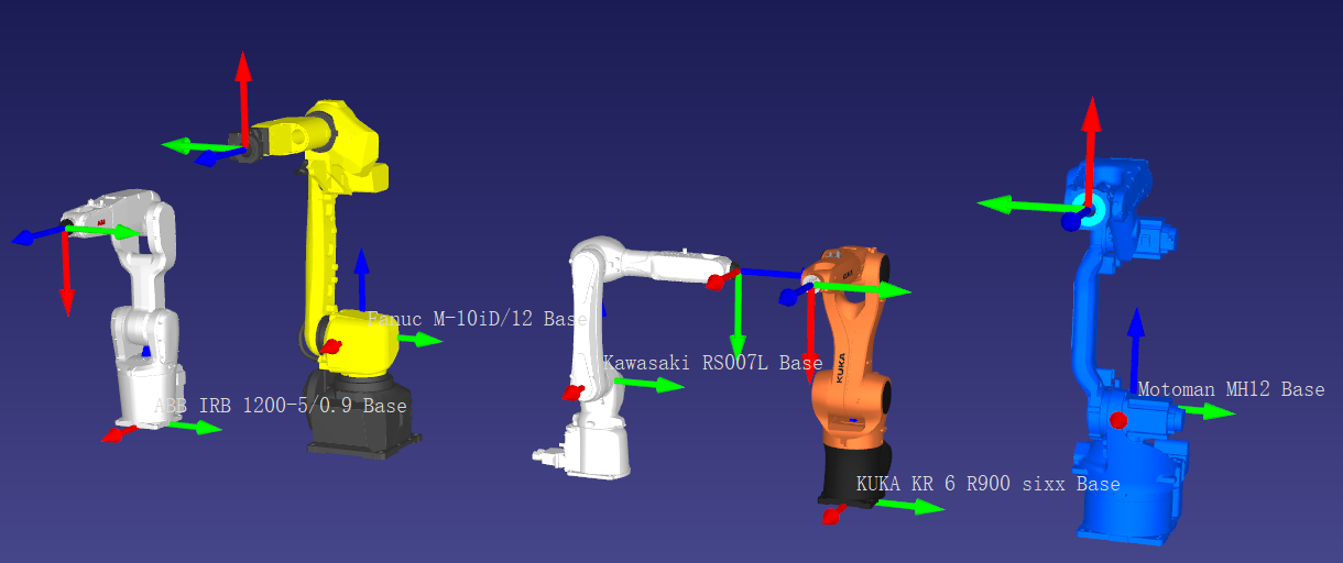
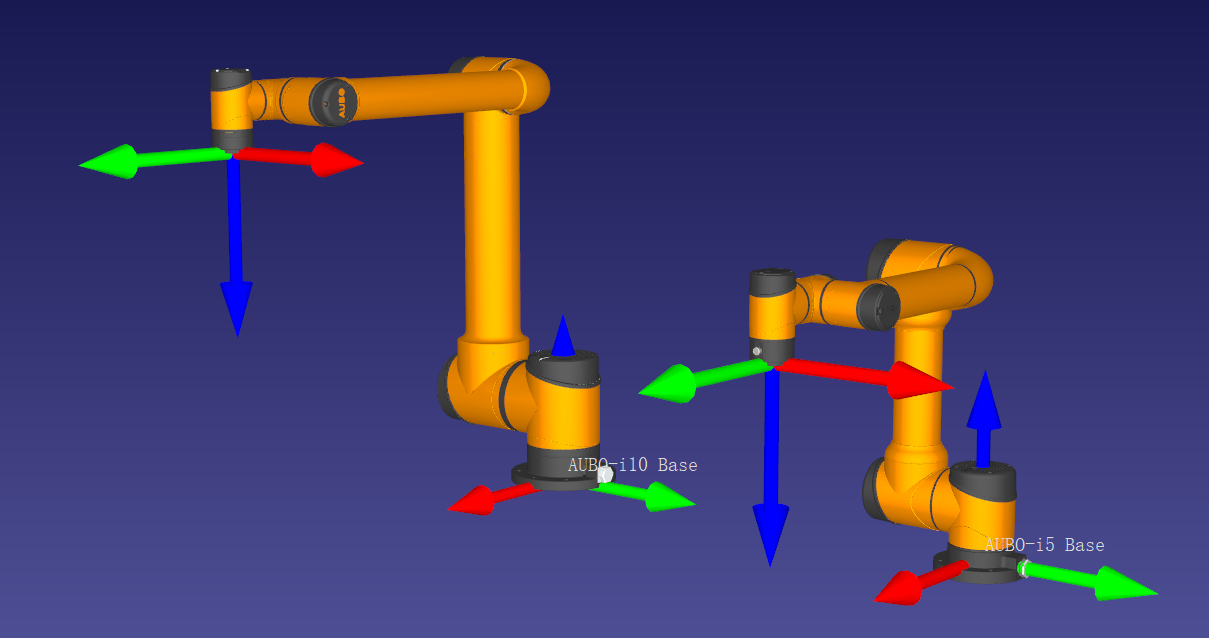
For some models, such as the AUBO i5 or certain robots from other manufacturers, the frame may be located slightly above the base (approximately 2 mm to 1 cm).
The orientation of the frame axes also differs among manufacturers:
-
ABB, FANUC, KUKA, YASKAWA: X-axis (red arrow in the figure) points toward the front of the robot.
-
KAWASAKI: Y-axis (green arrow in the figure) points toward the front of the robot.
| When deploying a vision system, it is recommended to first verify whether the reference frame used in the robot controller is the default robot frame or a user-defined frame before configuring the vision system. Because different manufacturers define the robot frame differently, the tool pose values displayed on the robot teach pendant may not match the values shown in Mech-Viz. Upon project startup, it is advised to compare the TCP between the robot and Mech-Viz. If discrepancies are found, you can adjust the relevant parameters by right-clicking the robot name in the Mech-Viz project resource tree, selecting Open Robot File Directory, and modifying the [robot]_algo.json file. |
Camera Reference Frame
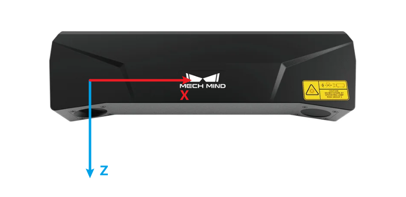
The camera reference frame is defined by the camera manufacturer and describes the position and orientation of objects within the camera’s field of view. It is commonly used for extrinsic parameter calibration to establish the spatial relationship between the camera and the robot frame, enabling vision-guided tasks and path planning.
The frame’s origin of Mech-Mind industrial 3D camera is typically located at the optical center of the main 2D camera. The axes of the reference frame are defined as follows: the Z-axis coincides with the optical axis of the camera, perpendicular to the imaging plane, and points in the imaging direction; the X-axis and Y-axis are parallel to the imaging plane, with their directions following the right-hand rule.
Target Object Reference Frame
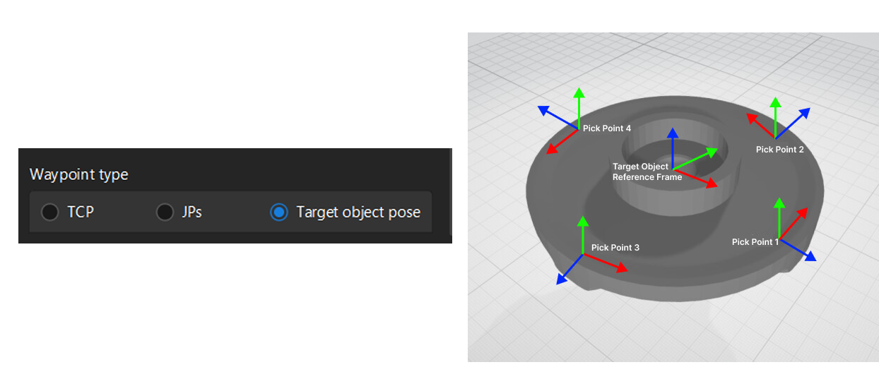
The target object reference frame serves as the fundamental frame of the target object, describing its position and orientation in space. Unlike the robot frame and camera frame, the target object frame is typically user-defined based on the target object geometry and task requirements. This allows adaptation for picking, placing, and rotational symmetry.
| In Mech-Viz versions 1.8.0 and earlier, the target object frame was defined at the object center point (geocenter). |
- Target object pick point
-
One or more pick points can be defined within the target object reference frame. These pick points will be output by Mech-Vision. When picking a target object, the robot moves its TCP to the pick point so that their origins and X-axes are aligned, while their Y-axes and Z-axes are oriented in opposite directions.
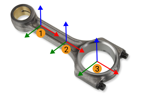
Among them, ① and ② are the pick points of shafts, while ③ is the pick point of ring center.
- Target object pose placement
-
When placing a target object based on its pose in Mech-Viz, the robot aligns the target object reference frame with the target pose defined in space. In other words, the target object reference frame serves as the reference point when placing the object based on its pose.
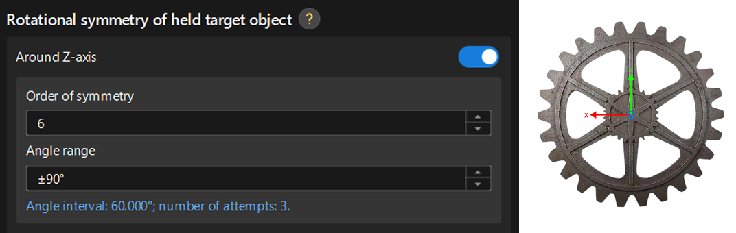
- Target object rotation symmetry
-
When the target object exhibits rotational symmetry, the rotation center is typically set to the origin of the target object reference frame. You can specify the coordinate axis of the reference frame as the rotation axis. For example, a gear has 60° rotational symmetry, and its rotation axis is the Z-axis of the target object reference frame. This configuration can be used to automatically generate rotation-symmetric pick points.
Tool Reference Frame
The tool reference frame is the coordinate system defined on the robot’s tool. Its origin is usually located at the tool center point (TCP).
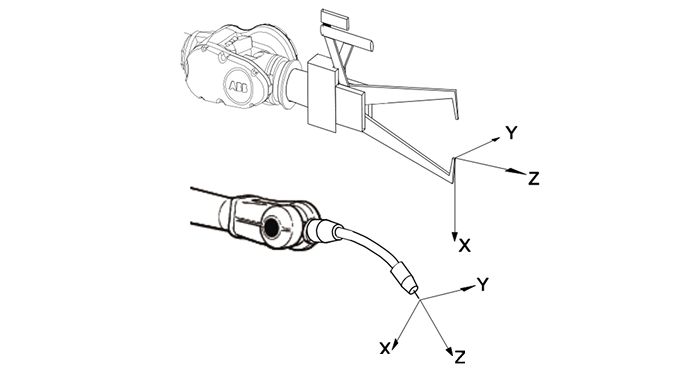
Through this reference frame, you can define the TCP, which is the pose of the tool reference frame in the robot reference frame, as well as the held target object pose, which is the pose of the target object reference frame relative to the tool reference frame when the object is being held. These definitions are used for pick planning and vision-guided tasks.