Pose
This topic introduces the basic concepts and common types of poses used in robot visual recognition, path planning, and motion control.
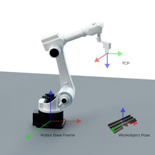
A pose represents both the position and the orientation of an object in 3D space. It describes the spatial relationship between one reference frame (such as a tool frame or target object frame) and another frame (such as the robot frame or camera frame). A pose typically consists of six components: X, Y, Z, Rx, Ry, Rz, corresponding to the 3D position and rotations around each coordinate axis.
Target Object Pose
The target object pose is the pose of a certain point on the target object relative to the robot base frame. When placing the target object, we usually make the its pose coincide with a certain target pose.
The target object pose is commonly used during 3D detection and pick planning. The vision system outputs the pose of the target object in the camera reference frame. Based on the hand-eye calibration result, this pose is transformed into the robot frame to determine the pick point or the assembly point in 3D space.
Robot Pose
A robot pose describes the robot’s position and orientation in 3D space. It is typically represented via either the TCP or the joint positions.
Tool Pose
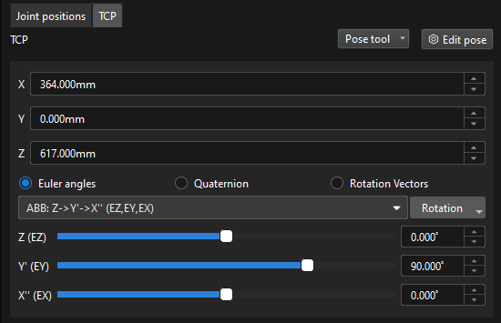
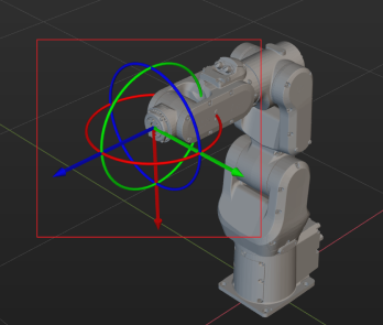
The tool pose describes the pose of the tool reference frame relative to the robot frame. It specifies the tool’s position (x, y, z) and orientation (often represented using Euler angles, a rotation matrix, or a quaternion).
The reference point of the tool pose is the TCP (Tool Center Point), which is the origin of the tool reference frame. The TCP is a reference point defined on the tool or externally, used to represent the tool’s position and orientation in space. Its pose is defined relative to the robot’s flange and is typically set at a key location on the tool, such as the center of a suction cup, the pick point of a gripper, or the tip of a welding torch. When the robot performs tasks such as picking, welding, or spraying, its motion is essentially moving the TCP to the target point.
-
Euler Angles
Euler Angels are used to describe the rotation of the object in the 3D space.
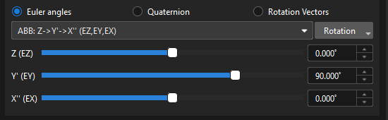
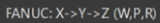
The Euler angles consist of three angles that correspond to the rotation of each of the three axes. These three axes usually rotate around the X, Y and Z-axis of the object’s fixed reference frame respectively. The same orientation can be expressed in different ways using multiple Euler angles. To avoid ambiguity, a consistent definition of Euler angles is applied in the robots from different brands. For more information on Euler angle conventions and representations, please refer to Euler Angles.

-
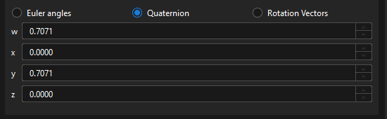
Quaternions
To avoid the gimbal lock problem of using Euler angles, some robot manufacturers use quaternions to represent the orientations in the space. A quaternion roughly refers to using three numbers to define the spatial rotation axis and using the fourth number to define the rotation angle. The tool reference frame can reach the target pose from its initial state by rotating the angle around the spatial rotation axis.
-
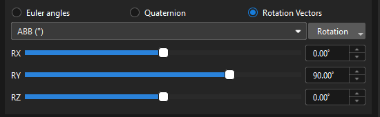
Rotation Vector
The rotation vector, also known as the axial angle, is used to describe the rotation state of the tool.
Currently, it is only used by UR robots.
The tool pose is a core parameter for both path planning and picking. At waypoints, target points, or during manual teaching, the pose you input and adjust is the tool pose. The robot then follows this pose, executing either linear or joint motions to perform picking, placing, or other tasks.
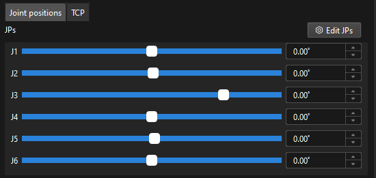
Joint Positions (JPs)
Joint positions refer to the rotation angles of each joint of the robot relative to its initial position or reference position. This description can represent the state of each joint in line with the hardware structure of the robot.
The joint positions are mapped to the tool pose by forward kinematics computation, while the tool pose is mapped to the joint positions by inverse kinematic computation.
In practice, joint positions are commonly used for forward kinematics calculations, inverse kinematics verification, and reproducing robot poses. In offline simulation, Mech-Viz determines the robot’s pose at each moment based on the joint positions. During communication, if the robot supports receiving JPs data, Mech-Viz can send the planned joint positions directly, ensuring the executed motion trajectory exactly matches the simulated one.
Flange Pose
The flange pose is the pose of the robot flange frame relative to the robot reference frame, whose representation is the same as that of the tool pose. It can be seen as a special tool pose that the TCP is at the center of the flange without any rotation.
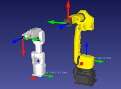
The default orientation of the flange reference frame defined by each robot manufacturer is different, resulting in different default angles for the flange pose. For example, the default X-axis orientation for ABB robots is downward, while that for FANUC robots is upward. In addition, most robots have a flange pose with the Z-axis perpendicular to the flange surface facing outward, but for the TURIN robots, it is the X-axis that is perpendicular to the flange surface facing outward.
The flange pose is primarily used for hand-eye calibration, tool installation, and pose verification. During hand-eye calibration, the flange pose can be used with the calibration board pose in the camera frame to calculate the extrinsic transformation. It is also commonly used as a reference when changing the tool or verifying TCP offsets.