Target Object Configuration Workflow When No Point Cloud Model Is Required
In this workflow, you can configure pick points, picking strategies, and collision models.
In the homepage of the target object editor, click Select under the No point cloud model required workflow to enter the configuration process. The overall configuration process is shown in the figure below.

-
Set pick point: Adjust the pick point or add an pick point array.
-
Set collision model (optional): Generate the collision model for collision detection during path planning.
The following sections provide detailed instructions on the configuration.
Set Pick Point
|
The target object model created through this workflow contains only one pick point. The pose of this pick point cannot be adjusted, and adding new pick points is not supported. |
Set Pick Point Array
When the target object is symmetrical, you can set the pick point array based on the object center point according to actual requirements. Setting the pick point array can prevent the robot’s end tool from unnecessary rotations during picking. This increases the success rate of path planning and reduces the time required for path planning, allowing the robot to move more smoothly and swiftly. The procedures for setting are as follows.
-
Under “Pick point settings,” click Generate next to Pick point array.
-
Refer to Rotational Symmetry of Target Objects to select the axis of symmetry, and then set the Order of symmetry and Angle range.
-
(Optional) Make vision result contain pick point arrays.
If disabled, Mech-Viz or the path planning tool will generate pick point arrays based on the settings in the target object editor and plan the path according to the pick points in the array. If enabled, Mech-Vision will output pick point arrays based on the settings in the target object editor, and Mech-Viz or the path planning tool will use the pick points in the array to plan the path.
-
If you hope pick point arrays can be generated and outputted before path planning, you should enable the option.
-
If you hope pick point arrays can be generated after path planning, you should disable the option.
In real situations, you can decide to enable or not to enable this option based on project requirements and the system performance. For instance, when the pick point array contains many points, it is generally recommended to enable this option to filter out invalid pick points before path planning and output optimized pick point arrays, so as to avoid excessively long path planning times and improve overall efficiency.
-
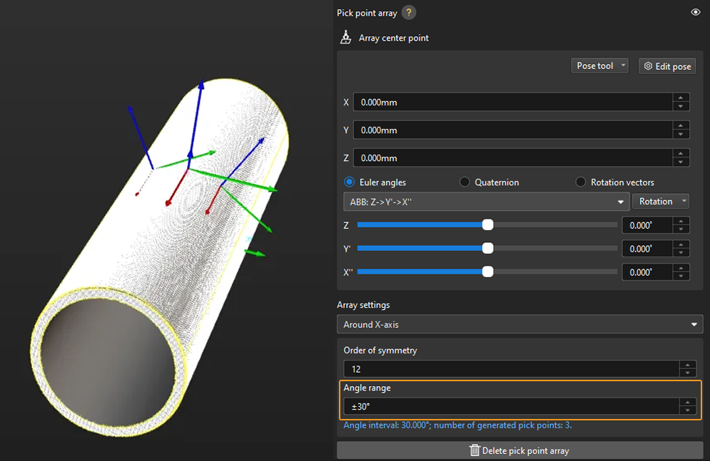
Taking a round tube as an example, the settings of the pick point array are as follows.
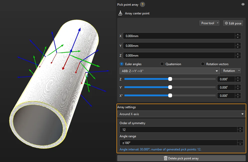
In practice, pick points with a downward Z-axis are often invalid and will affect path planning. Therefore, you should narrow down the Angle range. It is generally recommended to keep the range within ±90°. For example, when configuring a pick point array for randomly placed round tubes, the angle range value is set to ±30° in the figure below.
Add Picking Configuration
Preview Picking Effect
If a tool has been configured in the path planning tool or Mech-Viz, you can enable it in the target object editor to preview the positional relationship between the pick point and the tool during actual picking. This helps determine whether the pick point settings are appropriate. The detailed instructions are as follows.
-
Path Planning Tool
-
Mech-Viz
-
Add an end tool.
Add an end tool and set the TCP in the path planning tool.
-
Preview and enable the tool.
Once the end tool is added, the tool information will be automatically updated in the tool list within the target object editor. You can select a tool from the tool list based on your actual needs and preview the positional relationship between the pick point and the tool in the visualization area during actual picking (as shown in the figure below).
If the tool is modified in the path planning tool, please save the changes in the path planning tool to update the tool list in the target object editor. In addition, enabling the corresponding tool for the pick point in the target object editor is a prerequisite for successful path planning. 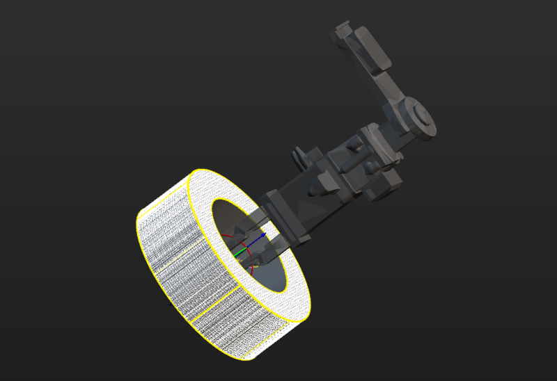
-
Ensure the Mech-Viz project is within the current solution.
To ensure that the end tool information in Mech-Viz can be updated in the target object editor, refer to Export Project to Solution to move the Mech-Viz project to the current solution.
-
Add an end tool.
Add an end tool and set the TCP in Mech-Viz.
-
Preview and enable the tool.
Once the end tool is added, the tool information will be automatically updated in the tool list within the target object editor. You can select a tool from the tool list based on your actual needs and preview the positional relationship between the pick point and the tool in the visualization area during actual picking (as shown in the figure below).
If you have modified the tool configurations in Mech-Viz, save the changes in Mech-Viz to update the tool list in the target object editor. In addition, enabling the corresponding tool for the pick point in the target object editor is a prerequisite for successful simulation in Mech-Viz.
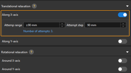
Configure Translational and Rotational Relaxation for Tools
In practice, to ensure the tool can still pick the target object after translating or rotating along a certain axis of the pick point, you can configure the translational relaxation and rotational relaxation for the tool in the target object editor.
Take the round tube as an example, the tool can be translated along the X-axis of the pick point while picking.
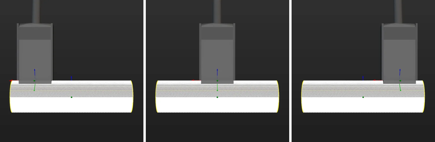
The corresponding configuration is shown below.
Set the Pick Point Selection Strategy
Minimum tool rotation will be used by default, and you can select a pick point selection strategy based on the actual requirements.
-
Minimum tool rotation: When this strategy is selected, the pick point that results in the smallest rotation of the tool’s Z-axis during the entire pick-and-place process will be selected with the highest priority. This strategy can prevent the tool from rotating in vain after picking the target object and avoid dropping the picked target object.
-
Minimum difference between tool and vision pose: When this strategy is selected, the pick point with the smallest angle difference from the target object pose will be selected with the highest priority.
-
Minimum collision between tool and point cloud: When this strategy is selected, the pick point that causes the least collision between the tool and the target object point clouds will be selected with the highest priority.
Now you can click Save to save the configurations for the target object. To set the collision model, click Next.
Set Collision Model (Optional)
Set Collision Model
The collision model is a 3D virtual object used in collision detection for path planning. The tool automatically recommends the collision model generating mode based on the current configuration workflow. The recommended mode for this case is Use common 3D shape. A collision model will be generated based on the selected common 3D shape for collision detection. Collision models generated by this method have low accuracy. However, the collision detection speed can be fast.
|
When the collision model is generated by Use common 3D shape, Detect collisions between held target object, point cloud, and unpicked target objects is not supported in Mech-Viz. |
Configure Symmetry of Held Target Object
Refer to Rotational Symmetry of Target Objects to select the axis of symmetry, and then set the Order of symmetry and Angle range.
Now, the collision model settings are completed. Click Save to save the target object to Solution folder\resource\workobject_library. Then the target object can be used in subsequent matching Steps.