Build a Workflow
After configuring the project resources, you can start to build the workflow.
Introduction
The workflow refers to the robot motion control program built in the flowchart form in Mech-Viz. Mech-Viz uses a graphical way to build workflows.
A workflow is formed by many Steps, and each Step represents a different robot programming module. You can select the Step you need in the Step library, drag it to the workflow editing area and define the logic and process of the program by setting parameters and connecting Steps, so as to create the logic to control the robot.
Mech-Viz provides plenty of Steps to meet the requirements of various industrial scenarios, such as robot motion control, vision system connection, vision result processing, DI/DO control, logical topology, logical judgment, picking, depalletizing, and communication.
Basic Procedures for Using Steps
| Objectives | Description |
|---|---|
Search for a Step |
Enter a keyword in the search box at the top of the Workflow panel or look in the relevant category for the Step you want. |
Add a Step |
Drag the Step from the Step library to the graphical programming workspace. |
Delete a Step |
Select the Step you want to delete and then press the Delete key; or right-click the Step you want to delete and select Delete in the context menu. |
Connect Steps |
Move the cursor onto the exit port of a Step and then drag the cursor to the entry port of another Step. |
Delete a Connection between Steps |
Click the connection you want to delete and then press the Delete key. Or you can select the connection, right-click it, and then select Delete in the context menu. |
Customize Description of the Step |
Right-click a Step and select Custom Description in the context menu. |
How to Build a Workflow
Usually, the robot motion path is formed by multiple waypoints. This section is a introduction to how to build a simple workflow with a path formed by two waypoints.
Follow these steps below to build the workflow:
-
Open Mech-Viz, click New blank project and select one robot model in the robot model library.
Skip the first step if you have already created a Mech-Viz project. -
Select Workflow in the bottom-right corner of the functional panels.
-
Find the “Fixed-Point Move” Step under the Basic Move category in the Workflow panel and then drag it to the right graphical programming workspace.
-
View the initial angles of robot joints under the JPs parameter on the right side. You can adjust the position of a joint by dragging the corresponding slider, and see the changes of robot pose accordingly in the 3D simulation area. The pose after adjustment can be taken as a waypoint.
-
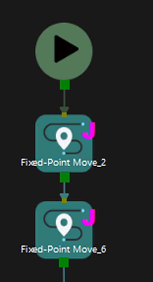
Connect the start icon with Fixed-Point Move_1. Click Simulate button in the upper-left corner of the software interface. The robot will move to the waypoint you set before.
-
Add another waypoint. Similarly, drag the Fixed-Point Move Step in the Workflow panel to the graphical programming workspace. Then, adjust the angle of a joint. Connect the output port of Fixed-Point Move_1 with the input port of Fixed-Point Move_2 and then click the Simulate button. The robot will move from one waypoint to another.
-
Connect the output port of Fixed-Point Move_2 with the input port of Fixed-Point Move_1 for a circular execution. The built workflow is as shown below.
|
As for building the workflow in complicated scenarios, please refer to Example Projects for more information.