Convert Point Cloud to Surface Data
Description
This Step is used to convert a 3D point cloud to two sets of surface data, top surface and bottom surface, by orthographic projection. The point cloud can be transformed beforehand for better projection results.
Methods for Transforming the Point Cloud
The geometric features (point, line, plane) input into the Step determine the method for transforming the reference frame of the point cloud.
The currently supported input combinations are as follows:
| When no geometric features are input into the Step, the point cloud will be transformed according to the settings in the Parameters section. |
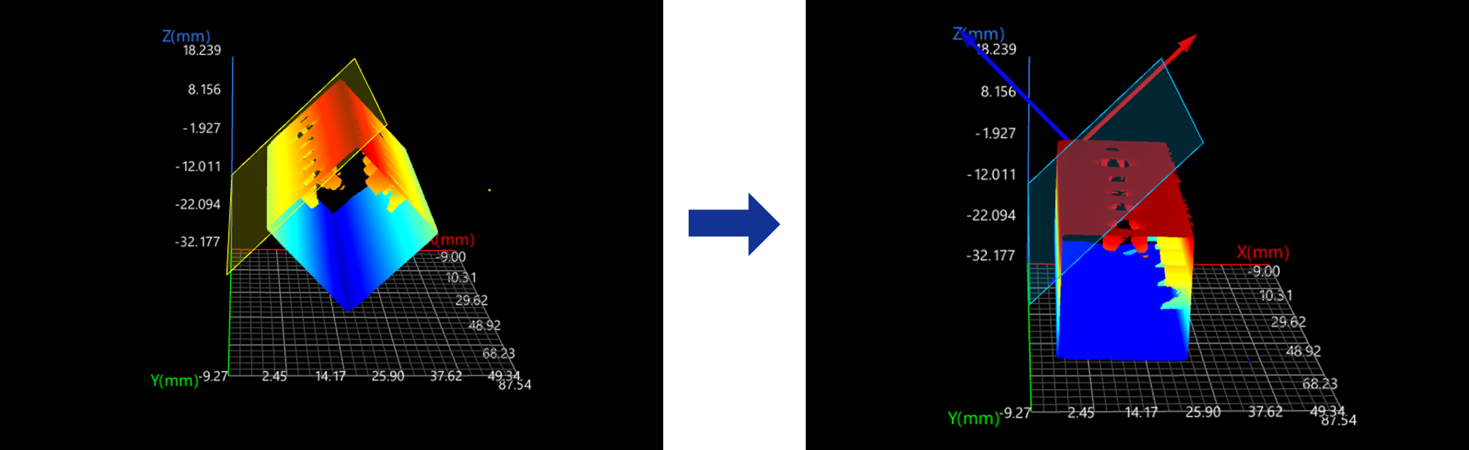
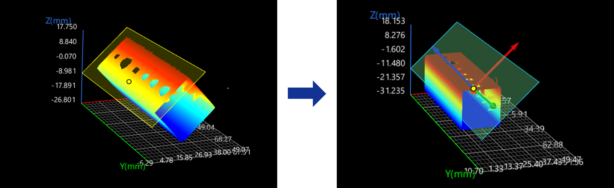
Plane
In the Input section, input a plane feature and leave the line and point features empty.
The reference frame in which the transformed point cloud resides is as follows:
-
XOY plane: the input plane.
-
X-axis: The new X-axis is parallel to the original X-axis.
-
Origin: The origin of the original reference frame is projected onto the input plane, and the projection becomes the origin of the new reference frame.
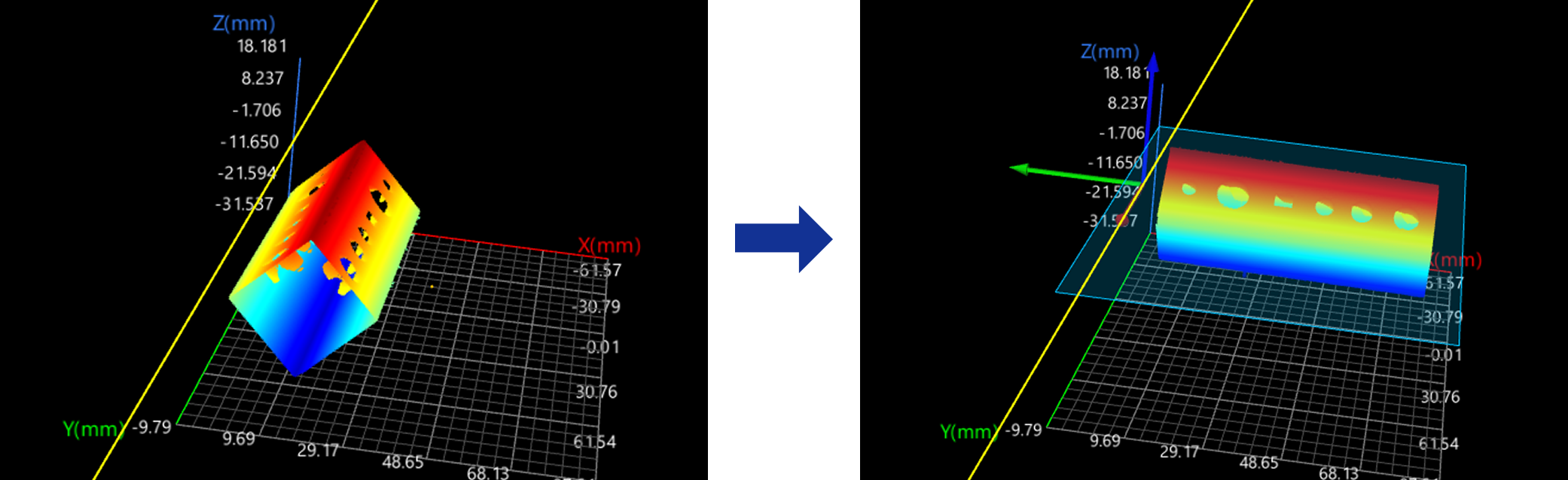
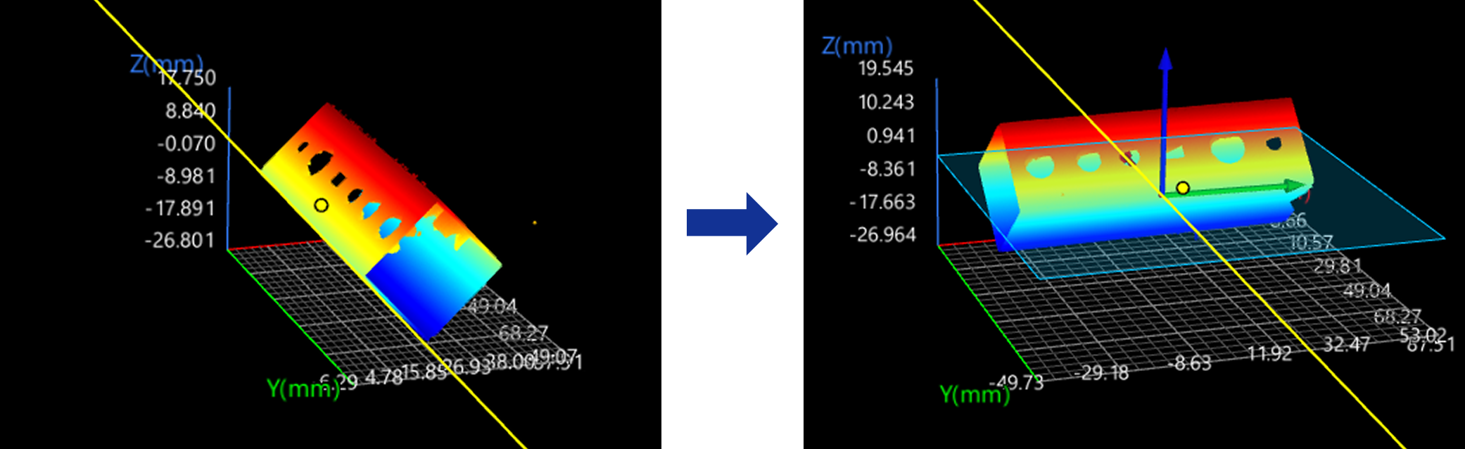
Line
In the Input section, input a line feature and leave the plane and point features empty.
The reference frame in which the transformed point cloud resides is as follows:
-
XOY plane: The cross product of the input line and the normal vector of the original XOY plane defines the Y-axis of the new reference. The new Y-axis and the input line form the XOY plane.
-
X-axis: the input line.
-
Origin: The origin of the original reference frame is projected onto the input line, and the projection becomes the origin of the new reference frame.
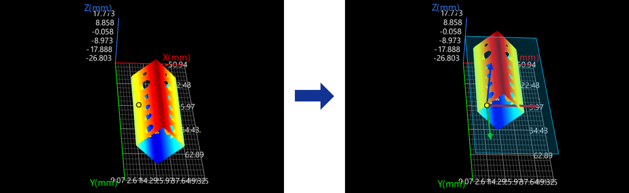
Point
In the Input section, input a point feature and leave the plane and line features empty.
The reference frame in which the transformed point cloud resides is as follows:
-
XOY plane: The new XOY plane, passing through the input point, is parallel to the original XOY plane.
-
X-axis: The new X-axis is parallel to the original X-axis.
-
Origin: the input point.
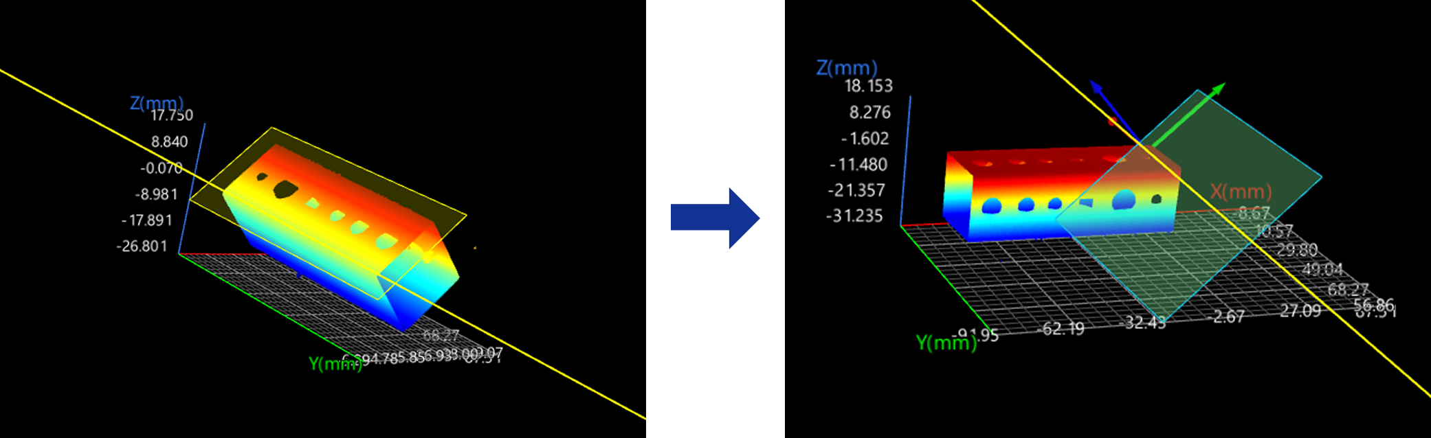
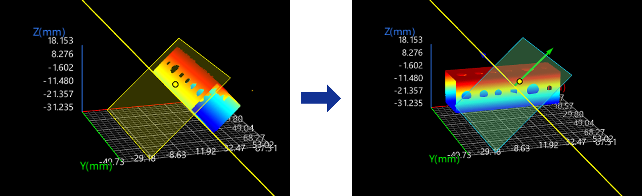
Plane + Line
In the Input section, input a plane and a line and leave the point feature empty.
The reference frame in which the transformed point cloud resides is as follows:
-
XOY plane: the input plane.
-
X-axis: the projection of the input line onto the input plane.
-
Origin: The projection of the original reference frame’s origin onto the projection of the input line, i.e., the new X-axis.
Plane + Point
In the Input section, input a plane and a point and leave the line feature empty.
The reference frame in which the transformed point cloud resides is as follows:
-
XOY plane: the input plane.
-
X-axis: The new X-axis is parallel to the original X-axis.
-
Origin: The input point is projected onto the input plane, and the projection becomes the origin of the new reference frame.
Line + Point
In the Input section, input a line and a point and leave the plane feature empty.
The reference frame in which the transformed point cloud resides is as follows:
-
XOY plane: The cross product of the input line and the normal vector of the original XOY plane defines the Y-axis of the new reference. The new Y-axis and the input line form the XOY plane.
-
X-axis: the input line.
-
Origin: The input point is projected onto the input line, and the projection becomes the origin of the new reference frame.
Plane + Line + Point
In the Input section, input a plane, a line, and a point.
The reference frame in which the transformed point cloud resides is as follows:
-
XOY plane: the input plane.
-
X-axis: the projection of the input line onto the input plane.
-
Origin: The input point is projected onto the input line, and the projection becomes the origin of the new reference frame.
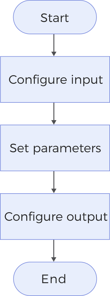
Workflow
The process of configuring this Step is as follows:
-
Configure the input. Connect the Step ports in the graphical programming workspace or select the input under Input in the parameter configuration panel.
-
Determine whether to add fixed transformations in the Parameters section.
-
Select the output items in the Output section.
Parameter Description
| Parameter | Description | ||
|---|---|---|---|
Add Fixed Transformations |
Select this parameter to add fixed transformations. After the point cloud is transformed to a new reference frame according to the geometric features input into the Step, the added fixed transformations can be applied. The description of the fixed transformation parameters is as follows:
|
Output Description
Select the output item(s) to add the output port(s) to the Step, and the corresponding data will be output after the Step is run. You can select the output according to the actual measurement requirements.
|
If you select an expandable output item, you should expand it by clicking ▶, and then set the Min and Max values to determine the acceptable range. If the output value falls within the acceptable range, the measurement item is judged as passing (OK), or else it is judged as failing (NG). |
| Output item | Description |
|---|---|
Top Surface Data |
The surface data visible when viewed from the positive Z-direction (top view). |
Bottom Surface Data |
The surface data visible when viewed from the negative Z-direction (bottom view). |
Alignment Parameter Group |
The alignment parameter group contains the rotation and translation information of the point cloud relative to the point cloud before transformation. This output can be used as an input to other Steps to synchronize the transformation of feature region(s). |
Troubleshooting
|
CV-W7204
Error: The set axial translation parameters are invalid.
Solution: Verify that the set values of the axial translation parameters are valid.
CV-W7205
Error: The set rotation angle about the X/Y/Z-axis is invalid.
Solution: Verify that the set rotation angles about the X/Y/Z-axis are valid.
CV-W7207
Error: Failed to calculate the X-axis of the new reference frame.
Possible causes:
-
The input geometric features are a line and a plane, and the line is perpendicular to the plane.
-
The input geometric feature is a plane, and the plane is parallel to the original XOZ plane.
Solutions:
-
When the input geometric features are a line and a plane, ensure the line is not perpendicular to the plane.
-
When the input geometric feature is a plane, ensure the plane is not parallel to the original XOZ plane.
CV-W7208
Error: Failed to calculate the Y-axis of the new reference frame.
Possible cause: The line input into the Step is parallel to the original Z-axis.
Solution: Ensure that the line input into the Step is not parallel to the original Z-axis.