Advanced: Detecting Small Defects in Large Images
For training scenarios involving large images with small defects, this document provides the computer casing data (click to download) to guide you through training a model using the Defect Segmentation module in Mech-DLK. The overall process includes seven steps: data collection, data processing, data labeling, image resizing, model training, model validation, and model export.
| You can also use your own data. Except for differences in the labeling stage, the overall usage process is the same. |
Preparations
-
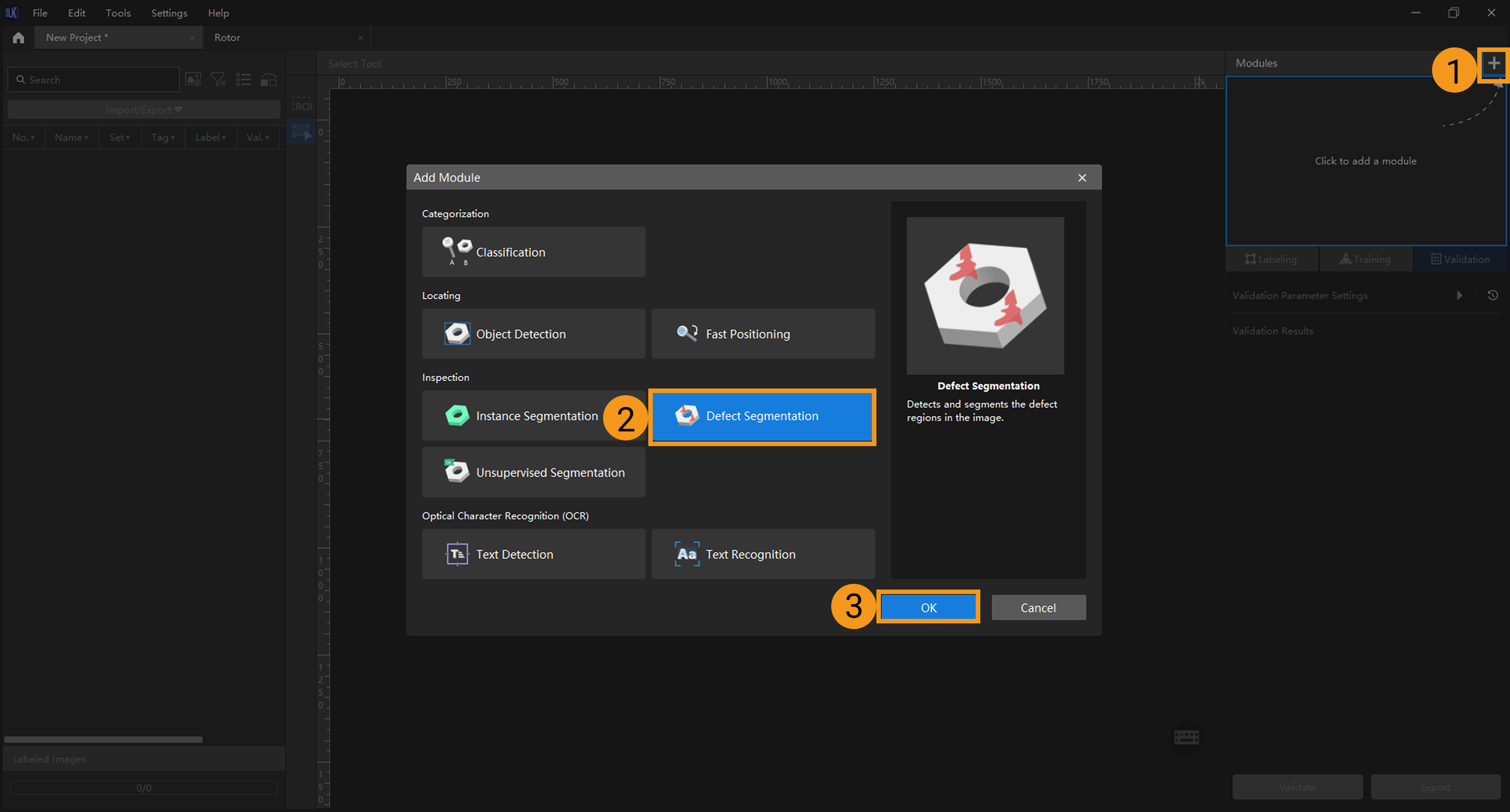
Create a new project and add the Defect Segmentation module: Click New Project in the interface, name the project, and select a directory to save the project. Click + in the upper right corner of the Modules panel and add the Defect Segmentation module.
-
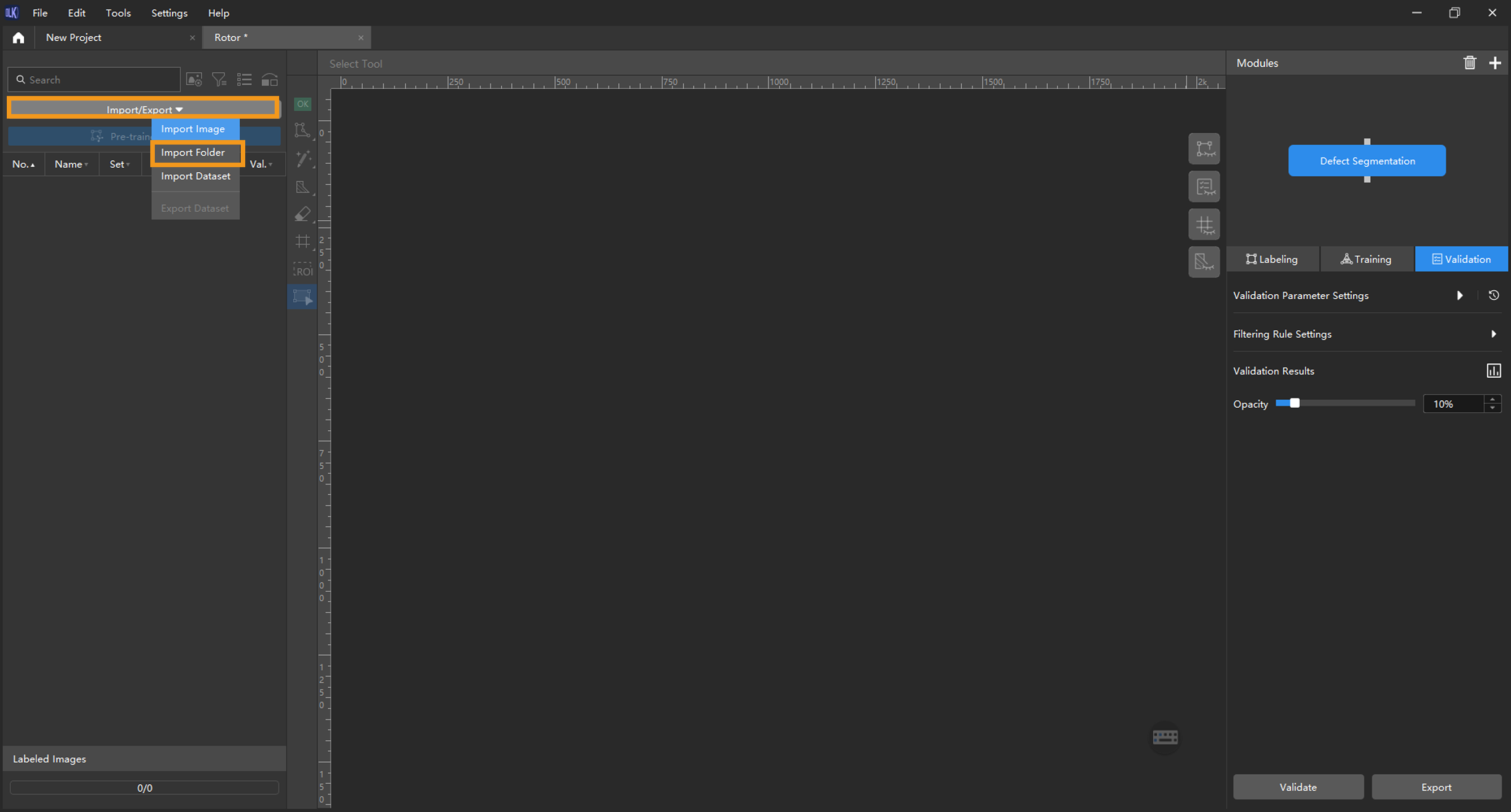
Import image data: Unzip the downloaded data package, click Import/Export at the top left, and then select Import Folder to import the image data.
-
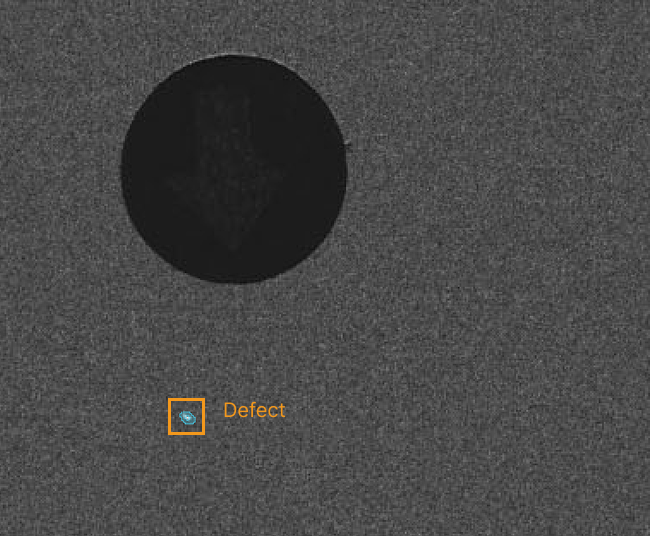
Browse images and analyze defect locations and characteristics: Review all imported images to analyze the locations and characteristics of defects. Bright spots on the laptop casing are considered defects and serve as the detection targets in this project. In this sample project, the defects in each image are small and appear in varying positions. Since the defect areas are clearly distinguishable from other areas, the ROI and mask tools are not applicable.
Data Labeling
-
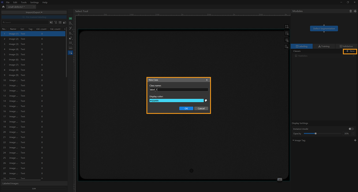
Create a new class: Since this project targets only one type of defect, a single class is sufficient.
-
Label images: As the target defects are very small, it is recommended to use the brush tool and adjust the brush size (preferably to the minimum value of 2). When labeling images, make sure to closely follow the shape of the defect. This project contains a large number of images. You can choose to label 10 images first and then start training.
You can hold down the Ctrl key and scroll the mouse wheel up to zoom in on the image for more precise labeling. -
Split training and validation sets: After labeling 10 images, move them to the training set. You can also include one defect-free image as an OK image in the training set to help the model distinguish between defective and normal images. Next, split the data into training and validation sets. In most cases, it is recommended to allocate 80% of the data for training and 20% for validation. The software will automatically split the labeled images that have been moved to the training set into 80% for training and 20% for validation.
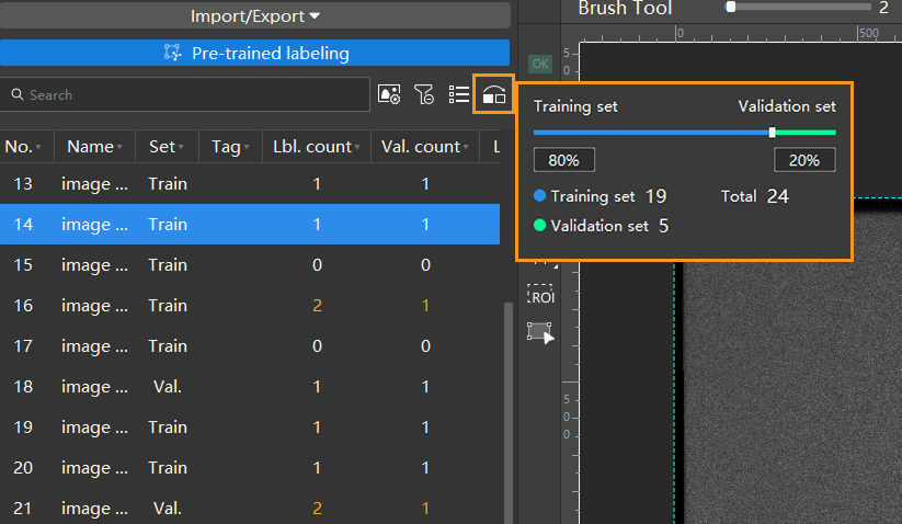
Image Resizing
-
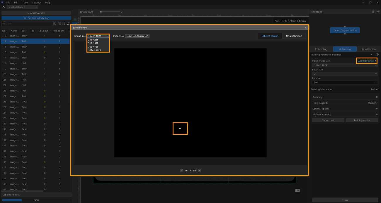
Enlarge images: Since the original images in this project are large and the target defects are very small, it is recommended to use the Input Image Size parameter to enlarge the images so that the model can clearly recognize the small defects. On the Training tab, you can click the Zoom Preview button to open a window and select an image size that clearly shows the labeled defects.
-
Use the Grid Cutting Tool: You can use the Grid Cutting Tool to split the original image into smaller cell images, increasing the proportion of labeled defects in each image and making it easier for the model to recognize them. Click the Grid Cutting Tool button in the labeling toolbar to launch the Grid Cutting Tool. You can set the number of rows and columns at the top of the image labeling section, and then click the Apply button to cut the image into equally sized smaller cell images. Set the number of rows and columns to both 3, as shown below.
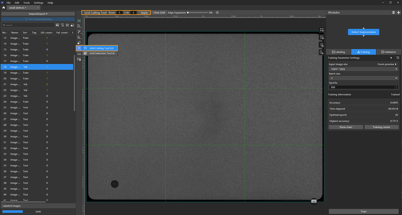
Please label the data before using the Grid Cutting Tool. -
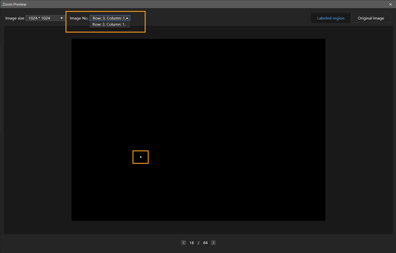
Preview and adjust input Image size: After clicking the Apply button, the Image size refers to the size of the cell images that will be fed into the neural network. If you need to verify the appearance of the cell images fed into the training model, you can reopen the Zoom Preview window, select the desired number of rows and columns at the top of the window, and view the scaled cell images accordingly. In this example project, the cut image is divided into nine equally sized cell images. The defect areas in both the labeled region and the original image are clearly visible within the cell images, indicating that the current input image size meets the requirements.
-
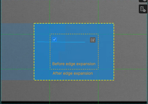
Use edge expansion (optional): If the labeled area is split across two grids after using the Grid Cutting Tool, you can use the Edge Expansion feature of the Grid Cutting Tool to drag the slider and enlarge the edges of each cell image until the entire labeled area fits within a single cell image. Edge expansion settings apply to all images.
-
Use the Grid Selection Tool: After cutting the image into multiple cell images, the number of images used for model training increases, which may slow down the training speed. To shorten training time, right-click the
 button in the labeling toolbar, select the Grid Selection Tool, and choose the images to include in training within the image labelling section. The appearance of the selected cell images is shown in the following image.
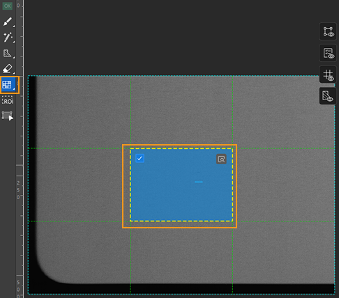
| By default, small images with defect labels are automatically included in the training, and all small images of OK images are also used for training. |
Model Training
-
Configure data augmentation parameters: Ideal training data should reflect various conditions encountered in actual production. For example, in this project, the image data should represent different lighting conditions on-site. However, since data collection may not cover all lighting scenarios, it is necessary to moderately expand the brightness range to enhance the model’s generalization capability. In this project, some defects are similar in color to the laptop casing. Therefore, it is necessary to moderately adjust both Brightness and Contrast parameters to ensure the training data reflects various on-site lighting conditions while making it easier for the model to recognize defects. Some defects are located near the edges of cell images or have colors similar to the surrounding areas, so using Rotation and Scale parameters is not recommended. Click the
 button on the right side of Training Parameter Settings under the Training tab to open the Data augmentation tab and configure the data augmentation parameters.
For detailed explanations of each parameter, see Train a Model.

-
Configure training parameters: In general, it is recommended to use the default settings for parameters such as Eval. interval, Learning rate, and GPU ID.
-
Model type: In this example project, the bright spot defects are small and have blurry contours, making them difficult to recognize. Therefore, it is recommended to use the High-accuracy model.
-
Epochs: When starting training for the first time, it is recommended to use a large number of epochs (500 or more) to fully train the model.
The input image size has already been set in previous steps, so there is no need to set it again at this point. Keep the remaining parameters at their default values. Click OK to save the settings.
-
When the input image size meets the requirements, using a smaller size can help speed up model training and inference.
-
Larger input image sizes help better fit the contours of validation and defect areas, improving model accuracy, but they also increase the number of training epochs and training time.
-
-
-
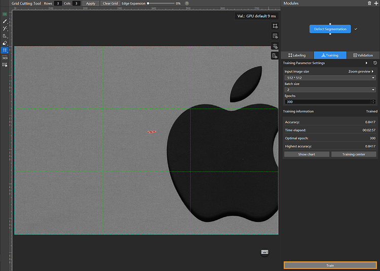
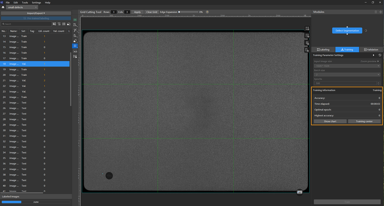
Start training: After configuring the parameters, click the Train button under the Training tab to begin training the model.
-
Monitor training progress through training information: On the Training tab, the training information panel allows you to view real-time model training details.
-
View training progress through the Training Chart window: Click the Show chart button and the Training center button under the Training tab to view real-time changes in the model’s accuracy and loss curves during training. You can wait for the model training to complete and then check the Highest accuracy parameter and the validation results on the test set to evaluate the model performance. An overall upward trend in the accuracy curve and a downward trend in the loss curve indicate that the current training is running properly.
-
Stop training (optional):
-
Based on the actual situation, you may optionally stop training early: When the model accuracy has reached the required level, you can stop training to save time. You can also wait for the model training to complete and observe parameter values such as the highest accuracy to make a preliminary assessment of the model’s performance.
-
If model training does not perform as expected, you can stop the training, troubleshoot the issue, and restart the training afterward.
-
Model Validation
-
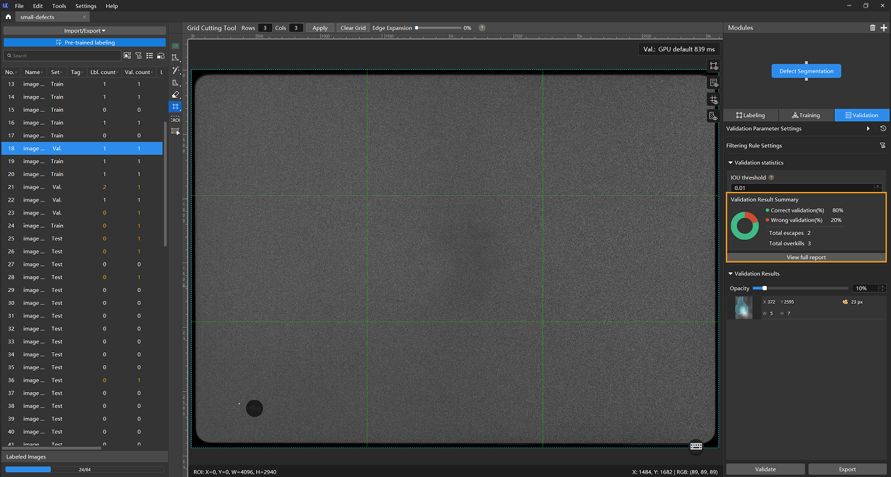
Validate the model: After training is completed or manually stopped, click the Validate button under the Validation tab to validate the model.
-
Restart training after troubleshooting when model performance is poor: For example, if the number of escapes or overkills is high after training and validation, indicating suboptimal model performance, you can reduce overkills by adjusting Filtering Rule Settings (such as the area filter), and reduce escapes by adding more labeled data. After making these adjustments, retrain and validate the model.
For images in the test set that have escapes or overkills, add labeled data and move the images to the training set for inclusion in the next round of training. When the model shows no escapes or overkills on the training set, it indicates that the model has initially acquired generalization capability.
You don’t need to label and move all images that have escapes or overkills in the test set into the training set. You can add labels to a portion of the images and include them in the training set to retrain and validate the model. Use the remaining images as a reference to observe the validation results and assess the performance of the model iteration. -
Export the model: Click Export. In the pop-up dialog box, select a directory to save the exported model, and click Export.
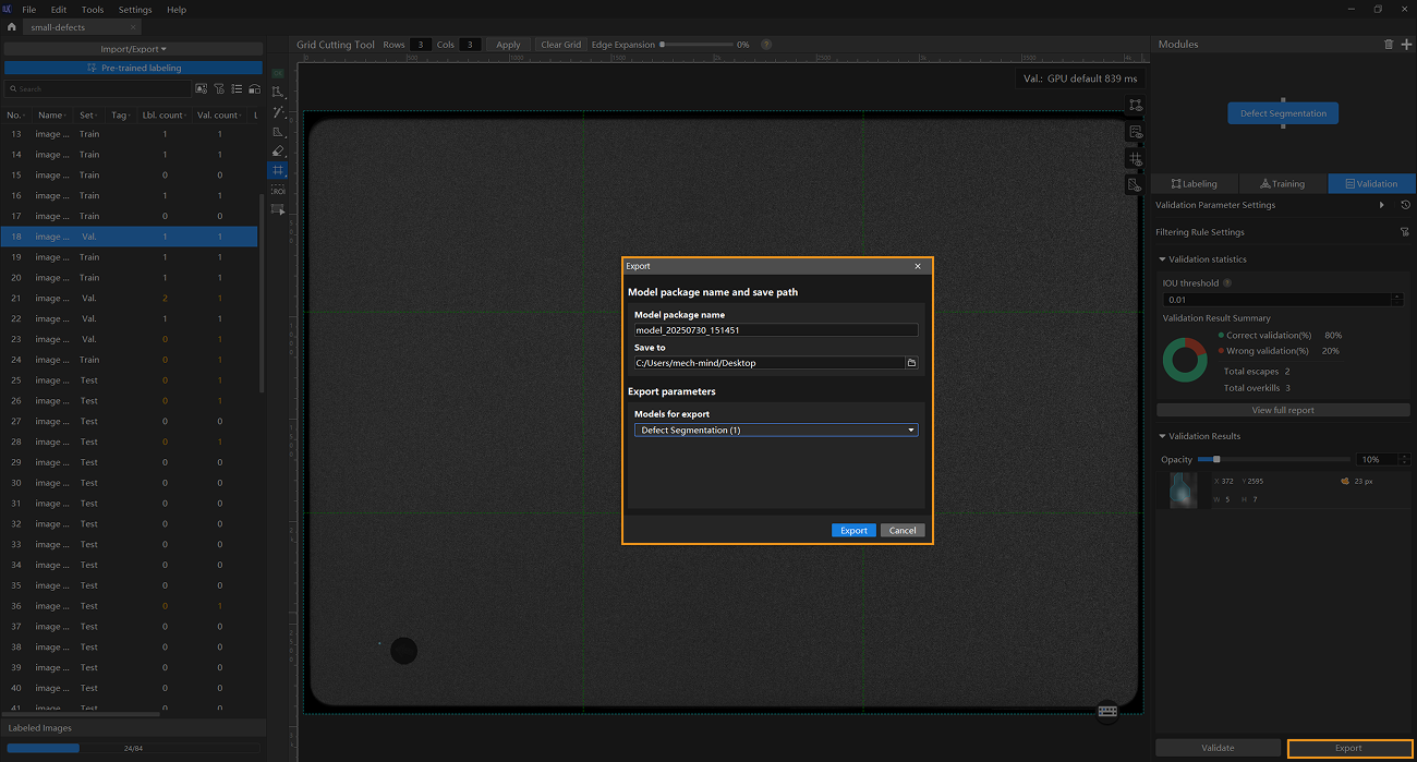
The exported model can be used in Mech-Vision and Mech-DLK SDK. Click here to view the details.