Hand-Eye Re-Calibration
The hand-eye calibration establishes the transformation relationship between the camera and robot reference frames (that is camera extrinsic parameters). With this relationship, the object pose determined by the vision system can be transformed into that in the robot reference frame, which guides the robot in performing its tasks.
|
When Is Hand-Eye Re-Calibration Needed?
During application deployment, hand-eye calibration has been completed, and the extrinsic parameters have been verified to meet the project’s accuracy requirements. However, hand-eye re-calibration is needed in the following scenarios:
-
When replacing equipment in the Vision System (such as a camera): The existing hand-eye relationship of the robot is no longer applicable, so hand-eye calibration needs to be redone.
-
When the robot’s working environment or layout changes: If changes in the environment affect the relative position between the camera and the robot, hand-eye calibration needs to be redone.
-
When the requirement for picking accuracy increases: If the original calibration results do not meet the on-site requirements, higher accuracy is needed.
-
When a collision or movement causes changes in the position of the robot or camera: Any physical changes that could affect the relative position between the camera and the robot require hand-eye re-calibration.
-
When issues with inaccurate picking arise and the extrinsic parameter errors increase: Degradation in extrinsic parameters may be caused by a decline in the accuracy of the camera’s intrinsic parameters or the robot’s accuracy. For information on how to assess extrinsic parameter errors, please refer to Methods for Analyzing Extrinsic Parameter Error.
-
After correcting the intrinsic parameters with the camera’s intrinsic calibration tool, you need to perform hand-eye calibration again.
-
For long-term application, to ensure system stability, it is necessary to periodically redo hand-eye calibration.
Methods for Analyzing Extrinsic Parameter Error
Analyze Extrinsic Parameter Error in ETH Setup
If the project has low requirements for picking accuracy (in the centimeter range), you can quickly determine if the extrinsic parameter errors are too large by “checking the overlap between the robot’s point cloud and the robot model in Scene Viewer”.
If the project requires high accuracy (within a few millimeters), you can evaluate the extrinsic parameters using the method “Analyze Extrinsic Parameter Error in ETH Setup”.
Roughly Check Coincidence Degree between the Point Cloud of the Robot and the Robot Model in Scene Viewer
You can check calibration results roughly by inspecting the coincidence degree between the point cloud of the robot and the robot model in Scene Viewer. The specific steps are as follows:
-
Move the robot body (its fifth axis is recommended) into the camera’s field of view.
-
Open Mech-Vision, select the project in the project list, and then click the Camera Calibration button in the toolbar. The Configuration before Calibration window will be prompted.
-
In the Select how to calibrate window, select the Load calibration parameters radio button, select the parameters that were calibrated for the project, and then click the Next button.
-
In the Select parameter usage window, select Continue working on the calibrated camera radio button, and then click the Next button.
Camera status should be displayed as connected. -
In the Select calibration task window, select the Re-calculate extrinsic parameters radio button, keep the Load the calibration data checkbox selected, and then click the Calibrate button. The Calibration window will be prompted.
-
In the Calculate extrinsic parameters step, click the Calculate extrinsic parameters button. This operation will trigger the camera to capture images and generate the point clouds of the robot.
-
Click Scene viewer to check the coincidence degree between the point cloud of the robot and the robot model.
If there is a significant deviation between the robot’s point cloud and the robot model, it indicates that the extrinsic parameter errors are large and re-calibration is needed.
Use the “Analyze Extrinsic Parameter Error in Eth Setup” Tool to Evaluate Extrinsic Parameters
Before evaluating the extrinsic parameters, please make sure that the calibration board is securely mounted on the last joint of the robot. After mounting the calibration board, select the in the menu bar, and then select in the Error Analysis window.
The procedure for evaluating extrinsic parameters using the “Analyze extrinsic parameter error in ETH setup” tool is as follows:
-
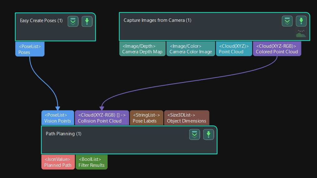
Build a new project for obtaining the calibration board poses. The project to be built is shown below:
-
Synchronize the pose of the real robot and obtain the scene point cloud containing the calibration board point cloud.
-
Select the “Path Planning” Step in the project, and click the Open the editor button on the Step Parameters panel to open the 3D simulation area.
-
Synchronize the pose of the real robot with that of the simulated robot in the “Path Planning” Step, so that the poses of the simulated robot in the 3D simulation area and the real robot will be the same.
-
Click the Simulate button to visualize the scene point cloud containing the calibration board. (Please ignore the error message after clicking Simulate.)
-
-
Create virtual TCP on the calibration board.
-
Add an end tool to the resources in the path planning tool.
-
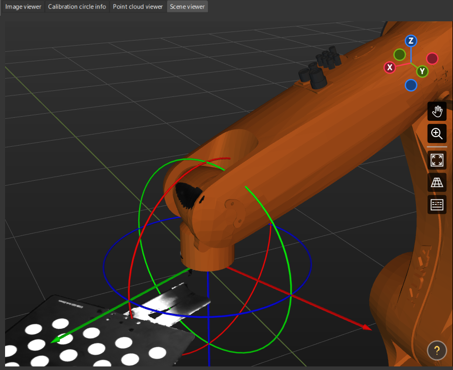
Check the visualization of the end tool in the 3D simulation area, and adjust the parameters to make the TCP coincide with a circle center on the calibration board (the pose axis should coincide with the cross in the circle and the XOY plane should be closely aligned with the calibration plane).
-
Enter a name and click OK to finish creating the virtual TCP.
-
-
Check extrinsic parameters at other positions in the workspace.
-
Move the real robot using the teach pendant to other positions in the workspace.
-
Synchronize the pose of the real robot with that of the simulated robot in the “Path Planning” Step, so that the poses of the simulated robot in the 3D simulation area and the real robot will be the same.
-
Click the Simulate button to obtain the new scene point cloud containing the calibration board.
-
Check if the virtual TCP added in the previous step coincides with the circle center on the calibration board.
-
If the deviation between the virtual TCP and the circle center of the calibration board is large, the extrinsic parameter error is large, and you need to perform hand-eye calibration again.
Analyze Extrinsic Parameter Error in EIH Setup
If the project has low requirements for picking accuracy (in the centimeter range), you can quickly determine if the extrinsic parameter errors are too large by “checking the overlap between the robot’s point cloud and the robot model in Scene Viewer”.
If the project requires high accuracy (within a few millimeters), you can evaluate the extrinsic parameters using the method “Analyze Extrinsic Parameter Error in EIH Setup”.
Roughly Check Coincidence Degree between the Point Cloud of the Robot and the Robot Model in Scene Viewer
You can check calibration results roughly by inspecting the coincidence degree between the point cloud of the robot and the robot model in Scene Viewer. The specific steps are as follows:
-
Move the robot end effector to a position where the camera can capture the robot base.
-
Open Mech-Vision, select the project in the project list, and then click the Camera Calibration button in the toolbar. The Configuration before Calibration window will be prompted.
-
In the Select how to calibrate window, select the Load calibration parameters radio button, select the parameters that were calibrated for the project, and then click the Next button.
-
In the Select parameter usage window, select Continue working on the calibrated camera radio button, and then click the Next button.
Camera status should be displayed as connected. -
In the Select calibration task window, select the Re-calculate extrinsic parameters radio button, keep the Load the calibration data checkbox selected, and then click the Calibrate button. The Calibration window will be prompted.
-
In the Calculate extrinsic parameters step, click the Calculate extrinsic parameters button. This operation will trigger the camera to capture images and generate the point clouds of the robot.
-
Click Scene viewer to check the coincidence degree between the point cloud of the robot and the robot model.
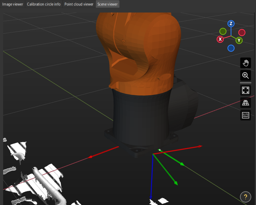
If there is a significant deviation between the robot’s point cloud and the robot model, it indicates that the extrinsic parameter errors are large and re-calibration is needed.
Use the “Analyze Extrinsic Parameter Error in EIH Setup” Tool to Evaluate Extrinsic Parameters
You can use the method “Analyze Extrinsic Parameter Error in EIH Setup” in the calibration tool to evaluate extrinsic parameter errors.
The detailed instructions are as follows:
-
Open Mech-Vision, select the project in the project list, and then click the Camera Calibration button in the toolbar.
-
In the Configuration before Calibration window, select the Load calibration parameters radio button, select the parameters that were calibrated for the project, and then click the Next button.
-
In the Select parameter usage window, select Continue working on the calibrated camera radio button, and then click the Next button.
Camera status should be displayed as connected. -
In the Select calibration task window, select the Re-calculate extrinsic parameters radio button, keep the Load the calibration data checkbox selected, and then click the Calibrate button. The Calibration window will be prompted.
-
In the Calculate extrinsic parameters step, click the Calculate extrinsic parameters button.
-
In the 2 Auxiliary tool area, click Extrinsic parameter accuracy to open the extrinsic parameter accuracy validation tool, and select "Analyze extrinsic parameter error in EIH setup."
-
Learn the instructions on evaluating the extrinsic parameter error in EIH setup, and then click the Next button.
-
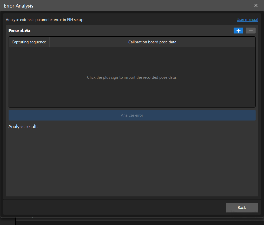
Click + to add multiple sets of calibration board poses.
-
Click the Analyze error button to view the result.
If the error is large (greater than the project’s picking accuracy requirements), you need to perform hand-eye calibration again.