Y-Axis Resolution of Scan Data
The Y-axis resolution of the scan data is the distance between two neighboring data points along the travel direction of the target object. This is equal to the distance between two neighboring profiles. The Y-axis resolution determines the accuracy of the scan data, as well as the aspect ratio of the target object in the intensity image and depth map.
The rate at which scanning is triggered determines the distance between two neighboring profiles, and therefore determines the Y-axis resolution of the scan data.
When you have specific requirement on the Y-axis resolution of the scan data, you can change the Y-axis resolution by adjusting certain parameters.
The parameters that affect the rate at which scanning is triggered differ depending on the value of Line Scan Trigger Source:
-
When scanning is triggered at a fixed rate: Trigger Rate determines the rate at which scanning is triggered.
-
When scanning is triggered by an encoder: Trigger Signal Counting Mode and Trigger Interval together determine the rate at which scanning is triggered.
The following sections explain the effect of the above parameters on the Y-axis resolution.
Trigger Rate
When scanning is triggered at a fixed rate, you can refer to the following equation and calculate the value of Trigger Rate for achieving the needed Y-axis resolution:
Y-axis resolution (μm) = travel speed of the target object relative to the laser profiler (μm/s) ÷ Trigger Rate
Trigger Signal Counting Mode and Trigger Interval
When scanning is triggered by an encoder, you can refer to the following equation and calculate the values of Trigger Signal Counting Mode and Trigger Interval for achieving the needed Y-axis resolution:
Y-axis resolution (μm) = encoder resolution (μm) × Trigger Interval ÷ Trigger Signal Counting Mode × 4
Among which, the encoder resolution is the travel distance (in μm) of the target object relative to the laser profiler during the duration of each signal in the following figure.
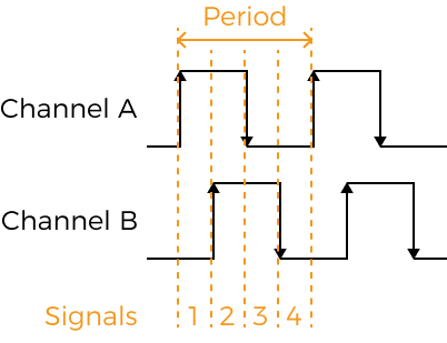
The following calculation example demonstrates how to determine the appropriate parameter values according to the above equation. You can also check the Detailed Explanation below to further understand how the two parameters affect the rate at which scanning is triggered.
Calculation Example
If the encoder resolution is 4μm, and the needed Y-axis resolution is 20μm, then:
20 = 4 × Trigger Interval ÷ Trigger Signal Counting Mode × 4
Simplify the above equation to get: 1.25 × Trigger Signal Counting Mode = Trigger Interval.
Therefore, the following parameter values can basically satisfy the requirement on Y-axis resolution:
| Trigger Signal Counting Mode | Trigger Interval |
|---|---|
1× |
1.25 (Round it to 1 or 2) |
2× |
2.5 (Round it to 2 or 3) |
4× |
5 |
Detailed Explanation
Trigger Signal Counting Mode and Trigger Interval together determine the rate at which scanning is triggered:
-
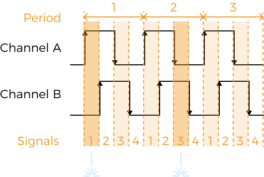
Trigger Signal Counting Mode determines how many signals in an encoder period is counted. The counted signals are the trigger signals.
-
Trigger Interval determines the interval (number of trigger signals) between line scans, that is, the number of trigger signals needed for scanning one line.
Using different parameter value combinations of the above two parameters, you can finely adjust the rate at which scanning is triggered.
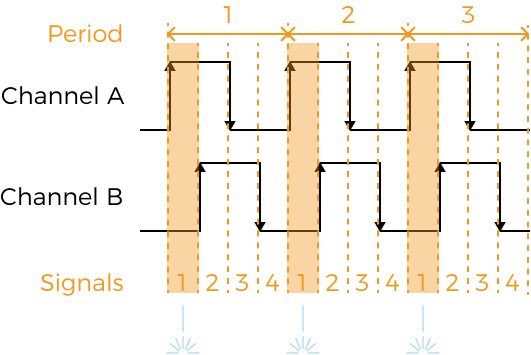
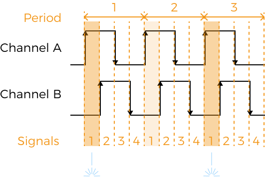
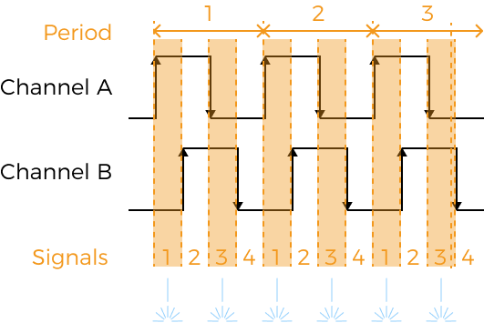
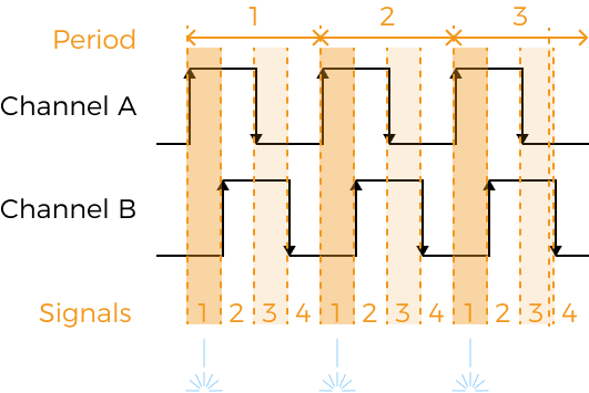
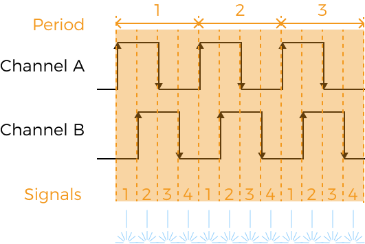
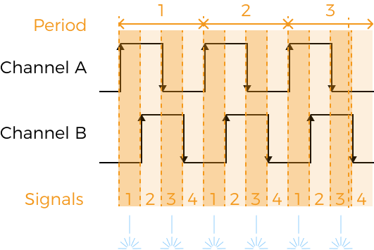
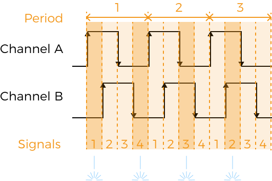
The following are the examples of some parameter value combinations. Orange indicates the counted signals (trigger signals), among which the darker orange indicates that the line scan is triggered during this signal.
| Trigger Signal Counting Mode set to 1× | ||
|---|---|---|
Trigger Interval set to 1: line scan triggered once every encoder period |
Trigger Interval set to 2: line scan triggered once every 2 encoder periods |
Trigger Interval set to 3: line scan triggered once every 3 encoder periods |
|
|
|
| Trigger Signal Counting Mode set to 2× | ||
|---|---|---|
Trigger Interval set to 1: line scan triggered twice every encoder period |
Trigger Interval set to 2: line scan triggered once every encoder period |
Trigger Interval set to 3: line scan triggered once every one and a half encoder period |
|
|
|
| Trigger Signal Counting Mode set to 4× | ||
|---|---|---|
Trigger Interval set to 1: line scan triggered 4 times every encoder period |
Trigger Interval set to 2: line scan triggered twice every encoder period |
Trigger Interval set to 3: line scan triggered 4 times every 3 encoder periods |
|
|
|
From the above examples:
-
When Trigger Signal Counting Mode is set to 4×, line scan can be triggered at higher rates. Meanwhile, because all encoder signals are counted, you can adjust the rate at which scanning is triggered more finely by adjusting Trigger Interval.
-
When the value of [Trigger Signal Counting Mode ÷ Trigger Interval] is the same, the rate at which scanning is triggered is also the same. For example, when the two parameters are set to the values below, the line scan is always triggered once every encoder period:
Trigger Signal Counting Mode Trigger Interval 1×
1
2×
2
4×
4
