HALCON: Connect to Camera, Perform Image Capturing, and Adjust Parameters
This topic provides instructions on connecting to a Mech-Eye Industrial 3D Camera, perform image capturing, and adjust camera parameters of the camera with HALCON image acquisition assistant and the HALCON sample provided by Mech-Mind.
Prerequisites
| For Nano (V3) and Pro XS (V3), it is recommended to connect the camera directly to the computer without using a network switch. |
-
HALCON 20.11 or above has been installed on computer.
| HALCON versions below 20.11 are not fully tested. |
-
Mech-Eye SDK 2.0.0 or above has been installed on computer.
| The version of the camera firmware must be consistent with that of Mech-Eye SDK. If not, please upgrade the camera firmware. |
-
The IP addresses of the camera and computer are in the same subnet.
| It is recommended to use static IP addresses. For instructions on setting the camera IP address, please refer to Set Camera IP Address with Mech-Eye Viewer. |
In HDevelop, you can connect to the camera with the image acquisition assistant or the sample provided by Mech-Mind.
Use Image Acquisition Assistant
Using the image acquisition assistant provided by HDevelop, you can quickly connect to the camera, perform image capturing and adjust camera parameters.
To open the image acquisition assistant: open HDevelop, and in the menu bar, select .
Connect to the Camera
-
In the Image Acquisition window, under the Source tab, select Image Acquisition Interface, and select GigEVision2 from the drop-down menu.
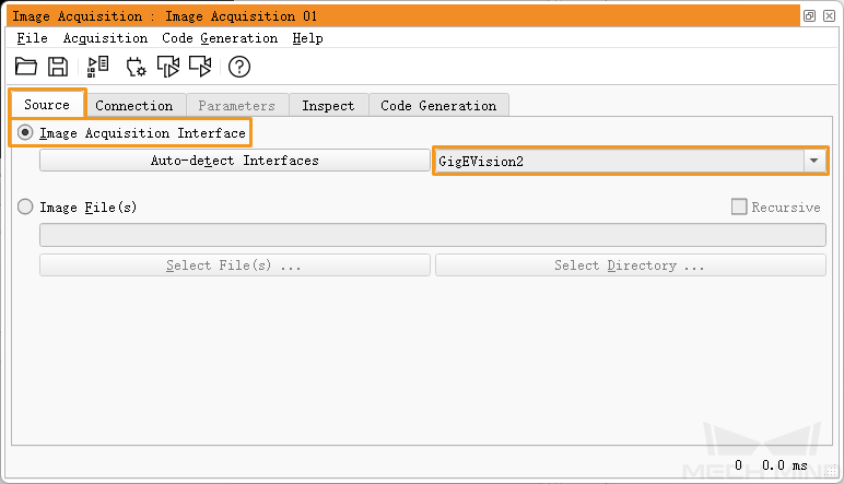
If the GigEVision2 option is unavailable, the GigEVision2 image acquisition interface is not installed. Please refer to HALCON’s Installation Guide and install the interface through MVTec Software Manager (SOM). -
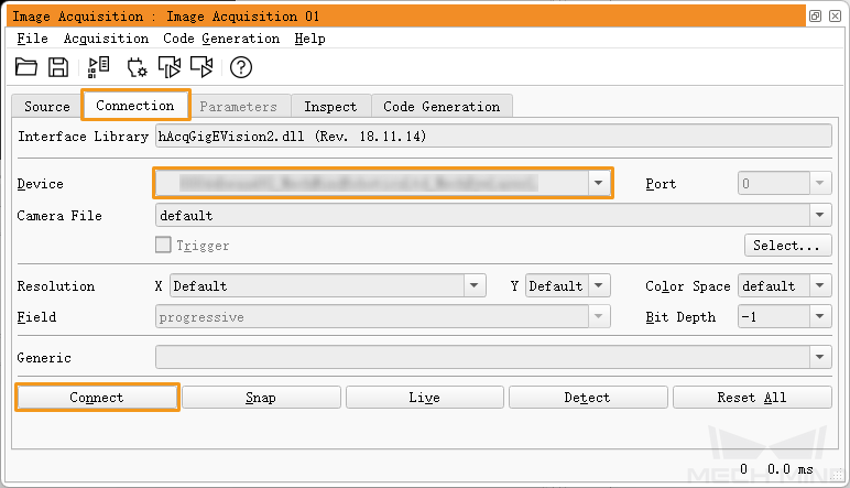
Under the Connection tab, from the drop-down menu of Device, select the device you would like to connect. Then, click Connect in the lower left.
|
Perform Image Capturing
To perform image capturing once: under the Connection tab, click Snap.
|
If the image capturing process takes too long, you can increase the MTU size of the camera, and enable jumbo frames on your computer. |
You can also perform image capturing multiple times or continuously. To do this, you need to adjust the AcquisitionMode parameter first.
-
To perform image capturing multiple times:
-
Switch to the Parameters tab, set the value of the AcquisitionMode parameter to MultiFrame.
-
Click Refresh in the upper right, and then set the number of times for image capturing in the AcquisitionFrameCount parameter.
-
Switch to the Connection tab and click Live to perform image capturing.
-
After the set times of image capturing are completed, the Live button becomes Stop. Click Stop to stop image capturing.
-
-
To perform image capturing continuously:
-
Switch to the Parameters tab, set the value of the AcquisitionMode parameter to Continuous.
-
Switch to the Connection tab and click Live to perform image capturing.
-
The Live button becomes Stop. Click Stop to stop image capturing.
-
|
Select Data Type
After the camera is connected, the 2D image is obtained by default. You can select whether to obtain 2D image or depth map by adjusting the DeviceScanType parameter.
-
Click the Parameters tab and find the DeviceScanType parameter. Set its value according to your needs. The parameter values are explained below:
Value Data type Areascan
2D image
Areascan3D
Depth map (an image containing depth information)
-
Perform image capturing to obtain the data type that you selected.
If Update Image in the upper right of the Parameters tab is checked, the image in the Canvas window is automatically updated as you adjust the parameters.
Set Capture Region
After the camera is connected, if you need to trim the obtained image, you can set a capture region by adjusting the Height, Width, OffsetX and OffsetY parameters.
To set a capture region, follow these steps:
-
Select the data type for setting a capture region.
-
Perform image capturing once with Snap to check the current image.
-
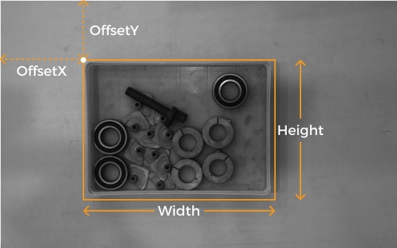
Switch to the Parameters tab and adjust the Height, Width, OffsetX and OffsetY parameters. The following figure shows the four parameters and the capture region defined (orange box) relative to the original image.
-
Width: the width of the capture region
-
Height: the height of the capture region
-
OffsetX: the x-coordinate of the upper-left corner of the capture region (the upper-left corner of the original image being (0, 0))
-
OffsetY: the y-coordinate of the upper-left corner of the capture region
The above four parameters must satisfy the following requirements:
-
(Width + OffsetX) not greater than the width of the original image
-
(Height + OffsetY) not greater than the height of the original image
The width and height of the original image are displayed in the WidthMax and HeightMax parameters under Read-only parameters (Visibility level must be set to Expert or higher).
-
-
-
Perform image capturing again to see the trimming result.
| If Update Image in the upper right of the Parameters tab is checked, the image in the Canvas window is automatically updated as you adjust the parameters. |
-
Switch to the Code Generation tab, click Insert Code to generate the corresponding code.
-
If you need to set a capture region for the other data type:
-
Disconnect from the camera in the current image acquisition assistant.
-
Open a new image acquisition assistant, and connect to the camera.
-
Select the other data type and repeat the above steps.
-
|
Comparison of Capture Region and Scan3DROI
Mech-Eye Industrial 3D Camera provides another set of parameters for setting an ROI: Scan3DROILeft, Scan3DROITop, Scan3DROIHeight, and Scan3DROIWidth (collectively referred to as “Scan3DROI”).
The differences between the capture region parameters and Scan3DROI parameters are summarized below. Please select the set of parameters that suit your needs.
| Capture region | Scan3DROI |
|---|---|
Not saved to parameter groups, reset if camera powered off |
Can be saved to parameter groups |
Applicable to 2D image and depth map |
Not applicable to 2D image |
Image is trimmed |
Image not trimmed |
Can only be set in HDevelop |
Can be set with visualized tool in Mech-Eye Viewer |
Adjust Parameters
If the quality of the obtained data is unsatisfactory, you can adjust the camera parameters under the Parameters tab.
|
To adjust the camera parameters, follow these steps:
-
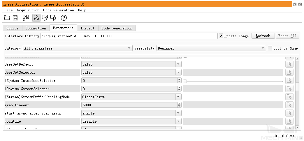
After the camera is connected, click the Parameters tab, set the UserSetSelector parameter to the parameter group that you want to modify.
-
Find the UserSetLoad parameter, and click Apply to the right to read in the configuration.
If parameter values are not updated after you click Apply, please click it again.
-
Find the parameter that you want to adjust and change its value.
-
Find the UserSetSave parameter, and click Apply to the right to save the configuration.
-
Switch to the Code Generation tab, click Insert Code to generate the corresponding code.
References
-
Camera parameters supported for GenICam generally correspond with those provided in Mech-Eye Viewer. For the parameter correspondence, descriptions and explanations of camera parameters supported for GenICam, please refer to Camera Parameters Supported for GenICam.
-
Setting camera parameters such as Auto-Exposure ROI, Depth Range and ROI usually requires the assistance of visualized tools for several rounds of fine tuning. Since HALCON does not provide visualized tools, you can set these parameters using the visualized tools provided by Mech-Eye Viewer. For detailed information, refer to Use Mech-Eye Viewer to Adjust Camera Parameters for GenICam Client.
| You must disconnect from the camera in HDevelop before you can connect to it in Mech-Eye Viewer and adjust parameters. If you fail to connect the camera in Mech-Eye Viewer, close HDevelop and try again. |
Use HALCON Sample
A series of HALCON samples are provided on GitHub. This section introduces how to use the connect_to_camera_and_capture_images sample to connect to a camera, perform image capturing, adjust camera parameters, and save the data. You can run the sample as is or modify it to better suit your needs.
|
The HALCON sample is written in C++ and can be executed in the HDevelop integrated development environment directly. |
Run the Sample
Please follow these steps to run the sample:
-
Download the connect_to_camera_and_capture_images sample: select .
-
Open the sample in HDevelop: Open HDevelop, and drag the sample into HDevelop.
-
Select the line containing the info_framegrabber operator in Program Windows, and click
 in the toolbar or press the F6 key to run this line.
 -
In the Control Variables area, double-click DeviceInfos to display a list of all the available cameras.

-
In the list, double-click the camera that you want to connect, and copy the camera name after unique_name: or user_name:.

user_name is the custom camera name. You can customize the camera name in Mech-Eye Viewer. -
Locate the following line, and replace MechEye with the copied unique_name or user_name.
DeviceInfo := 'MechEye' -
Run the sample by clicking
 in the toolbar or pressing the F5 key.
 -
If the sample is successfully executed, you can find the saved 2D image and point cloud in the folder where the sample is located. The default file names are image2d.bmp and PointCloud.ply.
|
Adjust Parameters
If the quality of the obtained data is unsatisfactory, you can adjust the camera parameters under the Parameters tab.
|
To adjust the camera parameters, follow these steps:
-
Use the following operator to obtain a list of available parameter groups.
get_framegrabber_param (AcqHandle, 'UserSetSelector_values', ParameterValues) -
View the list of parameter groups in the ParameterValues variable in the Control Variables area.
-
Use the following operator to select the parameter group to modify. UserSetSelector and UserSetLoad are the camera parameters used to select and load a parameter group, respectively. Replace ParameterGroupName with the actual parameter group name.
The parameter group name displayed in HALCON corresponds to the order of parameter groups in Mech-Eye Viewer. For example, UserSet0 in HALCON is the first parameter group in Mech-Eye Viewer. set_framegrabber_param (AcqHandle, 'UserSetSelector','ParameterGroupName') set_framegrabber_param (AcqHandle, 'UserSetLoad','ParameterGroupName') -
Use the following operator to obtain the value of the specified parameter. Replace ParameterName with the actual camera parameter name. ParameterValues is the variable used to save the parameter value, and you can change it according to actual needs. Note that this variable does not need to be included in parentheses.
get_framegrabber_param (AcqHandle, 'ParameterName', ParameterValues) -
View the parameter value in the ParameterValues variable in the Control Variables area.
-
Use the following operator to adjust the setting of the specified parameter. Replace ParameterName with the actual camera parameter name and NewParameterValue with the new parameter value.
set_framegrabber_param (AcqHandle, 'ParameterName', 'NewParameterValue') -
Use the following operator to save the parameter value modification into the parameter group. UserSetSave is the camera parameter used to save the parameter group. Replace ParameterGroupName with the actual parameter group name.
set_framegrabber_param (AcqHandle, 'UserSetSave', 'ParameterGroupName')
References
-
Camera parameters supported for GenICam generally correspond with those provided in Mech-Eye Viewer. For the parameter correspondence, descriptions and explanations of camera parameters supported for GenICam, please refer to Camera Parameters Supported for GenICam.
-
Setting camera parameters such as Auto-Exposure ROI, Depth Range and ROI usually requires the assistance of visualized tools for several rounds of fine tuning. Since HALCON does not provide visualized tools, you can set these parameters using the visualized tools provided by Mech-Eye Viewer. For detailed information, refer to Use Mech-Eye Viewer to Adjust Camera Parameters for GenICam Client.
You must disconnect from the camera in HDevelop before you can connect to it in Mech-Eye Viewer and adjust parameters. If you fail to connect the camera in Mech-Eye Viewer, close HDevelop and try again.