Installation Scenario Requirements
Based on the neatly arranged cylindrical shaft loading solution, this section explains the specific requirements of the solution in terms of the installation site, lighting conditions, power supply, and gas supply in detail.
Ground and Floor
Mech-Mind vision system is usually used in conjunction with robots, the conveyor system, machining centers, etc. Robots have high requirements for the ground or floors. The specific requirements are shown below.
-
Concrete ground and floor
Static load Material Concrete grade Concrete slab thickness ≥ 3 T/m²
Concrete
Not less than C30
Not less than 150 mm; 200 mm or more is recommended.
-
Tread plate ground and Floor
-
The static load at the robot mounting position should not be less than 3 T/㎡.
-
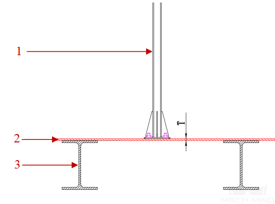
The support frame should be beneath the robot mounting position. The layout as shown in the figure below is prohibited, in which 1 represents the camera stand, 2 represents the tread plate, and 3 represents the support frame.
-
Installation Space
In actual applications, it is necessary to consider the requirements of the camera’s field of view, the robot’s picking space, and other interference factors. The specific requirements are as follows.
-
The clearance height of the workstation should be at least 4 m to ensure that the camera’s field of view can cover the picking area and that the robot has sufficient room to move.
-
Within the robot’s range of motion, columns or other obstacles should be avoided. This ensures that the robot can move freely without being restricted by obstacles.
-
When installing cameras, there should be no obstructions below the camera that interfere with the field of view. This ensures that the camera can capture the target objects properly and provide accurate vision information.
-
When planning the camera mounting position, it’s crucial to steer clear of obstructions like main beams, secondary beams, fire sprinkler systems, artificial light sources, or air ducts to ensure proper camera mounting and functionality.
Lighting Conditions
The lighting conditions on site will have a great impact on the 3D camera’s imaging effect. The specific influencing factors and solutions are as follows.
Factor 1: Too Much Lighting on Site
-
Description of the situation:
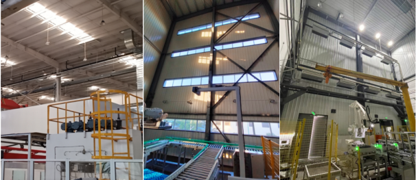
This factor will cause the image to be overexposed, and the camera will not be able to obtain qualified 2D images and point clouds. Common sources of strong light on-site are illustrated below.
-
Solutions:
-
To obtain good image data, it is recommended to use a laser camera ({lsr-s-} or LSR L-GL).
-
When the on-site lighting is too strong and the laser camera cannot meet the requirements, consider employing a shading solution. For details, please refer to Shading Solution.
-
Factor 2: Uneven Lighting on Site
-
Description of the situation:
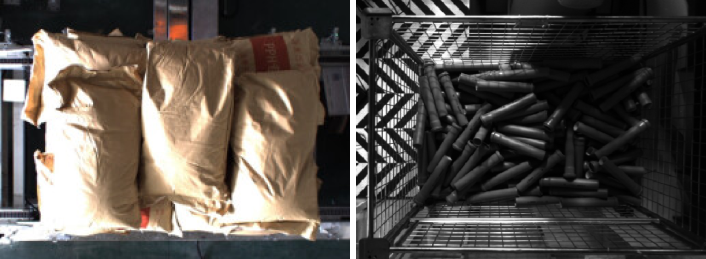
This factor will affect the deep learning recognition effect. The uneven lighting situation at the site is shown in the figure below.
-
Solutions:
Generally, this situation can be improved by constructing shading sheds or adding supplemental light. You can use a fill light with a color temperature of 6000 k, white ordinary LED bar light sources with adjustable light intensity, or surface light sources.
Factor 3: Uneven Lighting across Upper and Lower Layers
-
Description of the situation:
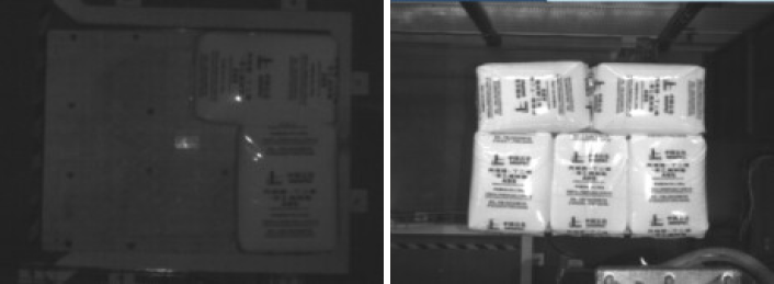
When the stack is higher than 2 m, the image of the upper-layer workpieces is overexposed, while the image of the lower-layer workpieces is underexposed, as shown in the figure below. This factor will affect the deep learning recognition effect.
-
Solutions:
This lighting condition can be improved by lighting the sides of the stack and adding a controllable light source to the top of the stack.
Power Supply Reference
| Power grid | Three-phase voltage | Frequency | Earthing system | Power consumption |
|---|---|---|---|---|
TN-S power supply system (3-phase, 5-wire, N, PE) |
380 V AC, ± 10% |
50 Hz, ± 1 Hz |
TN-S (the resistance value is required to be no more than 4 Ω) |
Single station power consumption not less than 14 kVA |
Compressed Gas (Provided by Customers)
For the use of compressed gases, dryness, cleanliness, and free-of-oil stains are key requirements. At the same time, attention should be paid to pressure stability, temperature control, and humidity control, and to ensure sufficient gas flow to meet vision system requirements. The specific requirements are as follows.
-
Clean, dry, and free-of-oil-stains: To ensure the normal operation of the vision system and extend the life of pneumatic components, compressed gas should be clean, dry, and free of oil stains by using suitable filters and dryers. Also, compressed gas should not contain organic solvents, salts, or corrosive gases.
-
Gas pressure: By using appropriate pressure regulators, the working pressure of the compressed gas should be between 0.6 MPa and 0.8 MPa, and the pressure fluctuation should be less than 10%.
-
Temperature and humidity: The temperature of the compressed gas should be between -5 °C and 70 °C. When the temperature is below 5°C, it is necessary to remove moisture to prevent freezing or other issues. Furthermore, the relative humidity should be controlled below 80% to avoid excessive humidity affecting the vision system.
-
Gas flow: Based on the selected pneumatic components and actual requirements, and through reasonable system design and selection of appropriate compressor specifications, ensure an adequate supply of compressed gas flow.
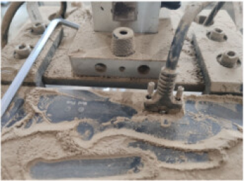
Environmental Dust
If the concentration of dust in the site environment is too high (as shown in the figure below), it will affect the operation of workstation equipment. Be careful of metal dust with a diameter smaller than 2.5 mm. Dust prevention measures must be taken to ensure the safety and hygiene of the workstation environment. The following part will introduce how to perform dust prevention for IPC and cameras.
IPC Dust Protection
In environments with a lot of dust, due to prolonged equipment operation, its surface temperature is higher than the ambient temperature, making it easy for dust particles to adhere to the surface of the equipment or exposed interfaces of electrical appliances (such as Ethernet ports of IPC), leading to poor contact, thereby affecting signal quality. In severe cases, it can even cause short circuits in components of the IPC. In this circumstance, dust prevention measures should be taken for the IPC and camera.
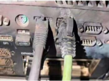
The image below illustrates an application example from a specific project where a large amount of metal dust adhered to the ports, resulting in damage. The port even sparked on-site, leading to irreparable damage to the internal components of the IPC. The interfaces and their cables of the monitor might also face similar damages.
Typically, the IPC is housed inside a cabinet, using the enclosed space for dust protection. However, in extremely harsh environments, dust can still enter the cabinet. Therefore, ensuring dust protection for the IPC cabinet is crucial in such situations.
-
Dust inside the cabinet mainly enters through:
Gaps on the cabinet surface. Since cabinets are assembled and welded from sheet metal, gaps are inevitable.
Unsealed cable ports, ventilation openings, and connections on the cabinet surface.
Fan openings on the cabinet surface.
-
Cabinet dust protection measures:
The cabinet body must be fully welded with sheet metal, and phenomena such as spot welding or intermittent welding are prohibited.
Cable ports can be sealed using brushes or conical rubber seals.
Considering the filtration level and airflow resistance, select appropriate grade dustproof mesh materials and perform regular inspections and maintenance to prevent blockages.
Camera Dust Protection
Using cameras in high-concentration dust environments can cause damage to the camera, affecting the camera’s imaging performance and lifespan. To address these issues, protective equipment can be mounted for the camera. Refer to Design of Camera Protective Equipment against High-Concentration Dust for the design method for camera protective equipment.