DC Power Extension Cable
Physical Specifications
Model |
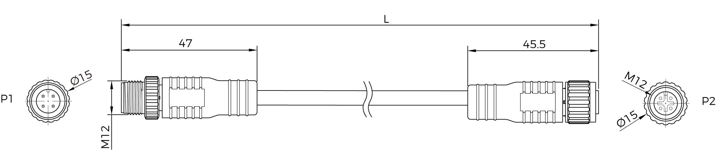
Straight connector |
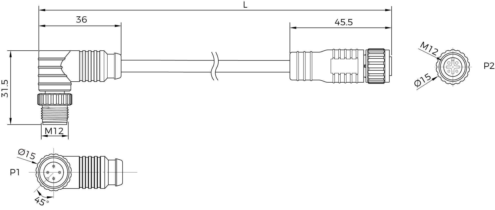
Right-angle connector |
|---|---|---|
CBL-PWR-EXT-5M
|
CBL-PWR-EXT-0.2M-LU
|
|
Color |
Black |
|
Jacket material |
PVC |
|
Outer diameter |
5.6 ± 0.15 mm |
|
Connectors |
M12-A, straight or right-angle, 4 pins
|
|
Wire gauge |
22AWG |
|
Minimum static bend radius |
22.4 mm |
|
Minimum dynamic bend radius |
44.8 mm |
|
Safety |
RoHS: compliant
|
|
Mobile tow chain test |
Bend cycles: ≥ 8 million |
|
Torsion test |
Torsion cycles: ≥ 3 million |
|
Can be used with |
DEEP-GL Log S
LSR S-GL LSR L-GL LSR XL-GL |
NANO-GL NANO ULTRA-GL PRO XS-GL PRO S-GL PRO M-GL UHP-140-GL |
Dimensions
Unit: mm
| Model | L | Tolerance |
|---|---|---|
CBL-PWR-EXT-0.2M-LU |
0.2 m |
± 20 mm |
CBL-PWR-EXT-5M / CBL-PWR-EXT-5M-LU |
5 m |
± 40 mm |
CBL-PWR-EXT-7M / CBL-PWR-EXT-7M-LU |
7 m |
± 70 mm |
CBL-PWR-EXT-10M / CBL-PWR-EXT-10M-LU |
10 m |
± 80 mm |


Usage Notes
-
The entire cable, consisting of a DC power cable and DC power extension cables, is recommended to include no more than three segments (one DC power cable and up to two extension cables), with a total length not exceeding 30 meters. If the total length exceeds 30 meters but does not exceed 60 meters, the DC output voltage of the DIN rail power supply should be increased to 26 V.
-
The connectors at the connection point must be securely tightened to ensure a firm threaded connection. The recommended tightening torque is no less than 0.7 N·m.
-
The connection points must be secured by using clamps or cable ties. To prevent movement during equipment operation, it is recommended to fix the connection points to the rigid structure of the robot arm or a fixed base on the ground.
-
Do not fix the connection points within the moving section of the track chain.