Getting Started
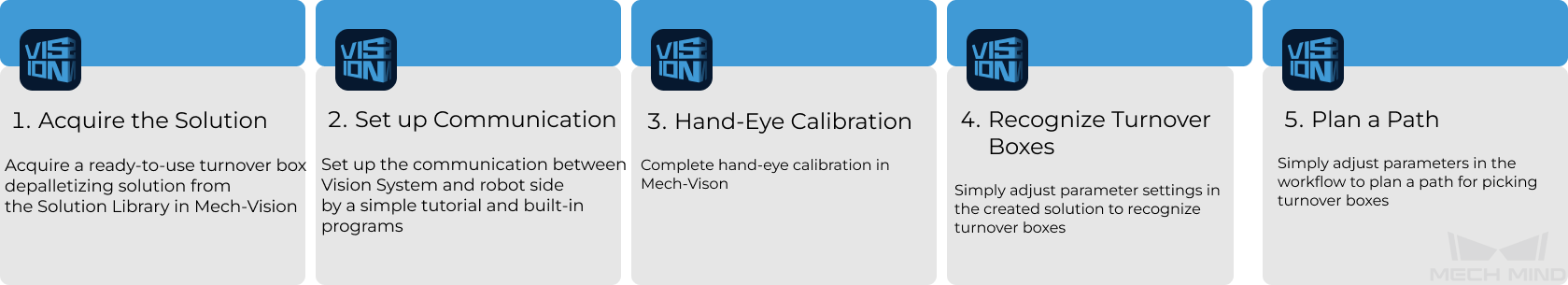
This section will introduce how to easily depalletize turnover boxes from a beginner’s perspective. The overall process is shown in the figure below.
Acquire the Solution
-
Open Mech-Vision.
-
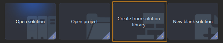
In the Welcome interface of Mech-Vision, click Create from Solution Library to open the Solution Library.
-
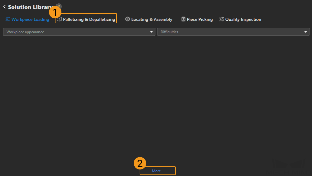
Click Palletizing & Depalletizing in the Solution Library, then click on More at the bottom, and click Yes in the pop-up window.
-
After acquiring the solution resources, select Turnover Boxes (with Production Interface). Then, fill in the Solution name and Path at the bottom, and finally click Create to download the turnover box depalletizing solution.
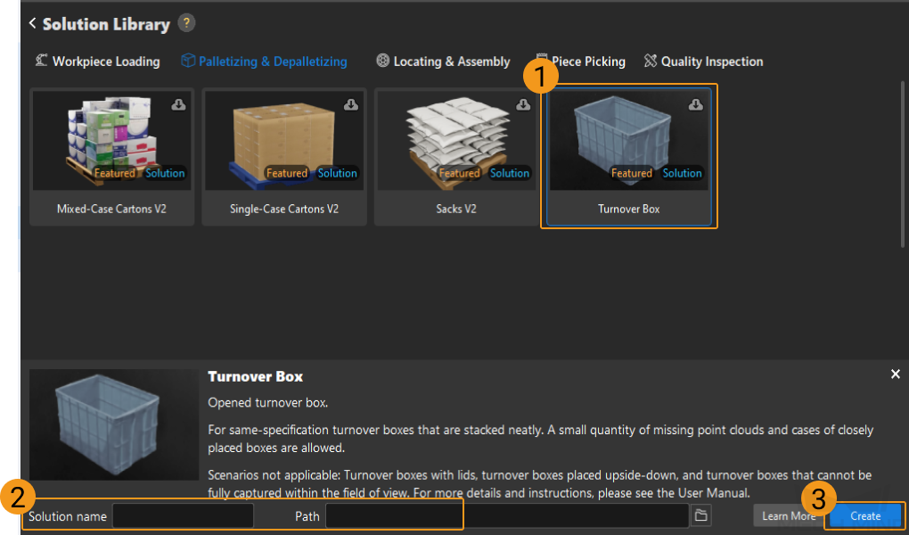
Once the solution is downloaded, it will be automatically opened in Mech-Vision.
Set up Communication
When deploying a Mech-Mind vision solution, you need to set up the communication between the Mech-Mind Vision System and the robot side (robot, PLC or host computer).
The turnover box depalletizing solution uses Standard Interface communication. For specific operations, please refer to Standard Interface Communication Configuration.
Hand-Eye Calibration
Hand-eye calibration establishes the transformation relationship between the camera and robot reference frames. With this relationship, the object pose determined by the vision system can be transformed into that in the robot reference frame, which guides the robot to perform its tasks.
Please refer to Hand-Eye Calibration Guide to complete hand-eye calibration.
|
Every time the camera is mounted, or the relative position of the camera and the robot changes after calibration, it is necessary to perform hand-eye calibration again. |
Locate Turnover Boxes
After completing the communication configuration and hand-eye calibration, you can use Mech-Vision to recognize turnover boxes. The process for turnover box recognition is shown in the figure below.

Connect to the Camera and Capture Images
-
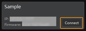
Connect to the camera.
Open Mech-Eye Viewer. Find the camera to be connected and click Connect.
-
Set the parameter group.
Click the dropdown arrow next to the Parameter Group on the right-hand side and select the Typical turnover box depalletizing.
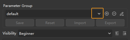
In addition to the default parameter group, Mech-Eye Viewer will also display parameter groups of other typical solutions.
-
Capture Images.
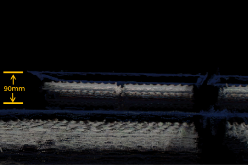
After the camera is successfully connected and the parameter group is set, you can start capturing turnover box images. Click the
 button on the top to capture a single image. At this time, you can view the captured 2D image and point cloud of the turnover box. Ensure that the 2D image is clear, the turnover box point cloud is intact, and the edges are clear. The qualified 2D image and point cloud of the turnover box are shown on the left and right in the figure below respectively.
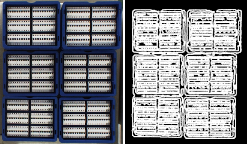
-
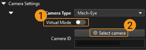
Add a camera in Mech-Vision.
Select the Capture Images from Camera Step, disable the Virtual Mode option, and click Select camera on the Step Parameters tab.
In the pop-up window, click the
 button on the right of the Camera ID. When the button turns into
  , the camera is connected successfully.
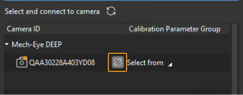
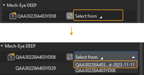
After the camera is connected successfully, you can click Select from and select the corresponding camera calibration parameter group, as shown below.
Once the above settings are complete, you can connect to a real camera. Other parameters can remain at their default values. Click the
 button on the right of the “Capture Images from Camera” Step to run this Step. If no error message occurs, the camera is connected successfully and images can be captured normally.
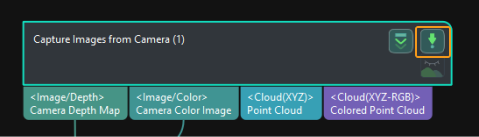
Extract Point Cloud of Turnover Boxes
-
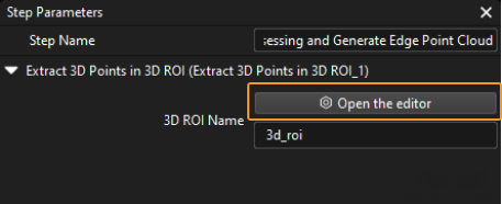
Select the Point Cloud Preprocessing and Generate Edge Point Cloud Procedure, then click the Open the editor button on the Step Parameters tab to open the Set 3D ROI window.
-
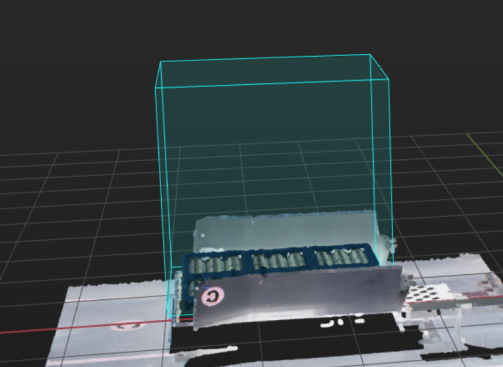
In the Set 3D ROI window, drag the default generated 3D ROI in the point cloud display area to a proper position. Make sure that the highest and lowest areas of the turnover box stack are within the green box at the same time, and that the green box does not contain other interfering point clouds, as shown in the following figure.
Calculate Turnover Box Poses Using 3D Matching
Make the Point Cloud Model
The specific methods for making surface point cloud models and edge point cloud models are as follows.
Make Surface Point Cloud Model
-
Generate point cloud model. This feature generates a point cloud from depth map(s) acquired by the camera. For specific operation, please refer to Generate a Point Cloud Model from Image Acquired by the Camera.
-
Edit the point cloud model. Ensure that only one turnover box point cloud is left after the outliers and point cloud of other turnover boxes are removed. For specific operation, please refer to Edit Point Cloud Model.
Make Edge Point Cloud Model
After making the surface point cloud model, you can use this to create edge point cloud model.
-
Select surface model in the resource list, and then click
 . You can use the “Estimate point could edges by 3D methods” to generate turnover box edge model.
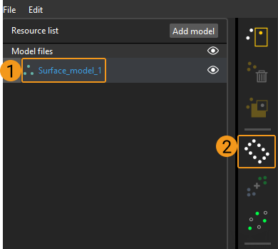
-
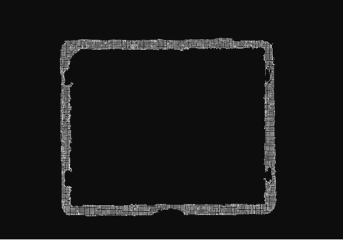
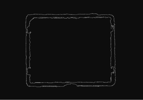
The generated edge point cloud model is as follows.
|
You can rename the point cloud model files by double-click them in the resource list. For example, you can rename them as Edge_model_1、Surface_model_1 for distinction. |
Add Pick Point
After you finish making the point cloud model, you can add a pick point for it.
-
Select surface model in the resource list, click
 to add pick point for surface point cloud model. The position and orientation of the pick point should then be adjusted to ensure that the pick point is as close as possible to the center of the surface point cloud model (as shown in the left figure below) and that the Z-axis is perpendicular to the surface of the model (as shown in the right figure below).
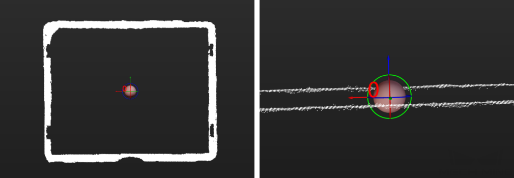
-
After adding the pick point of the surface point cloud model, right-click the pick point in the resource list, and then click Copy.
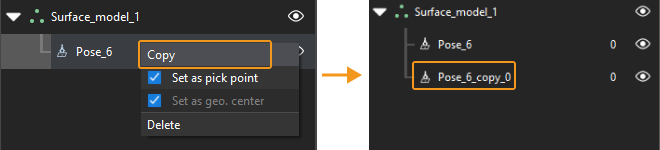
-
You can quickly add a pick point for an edge point cloud model by dragging the copied pick point below the edge point cloud model in the resource list.
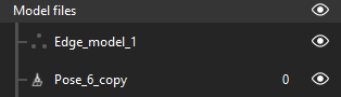
If you need to adjust the pick point later, you need to adjust the pick point of both the Edge Point Cloud Model and Surface Point Cloud Model.
Set the Layer Height
The Layer Height Indicates the height range of the highest layer area. Once the height range of the objects on the highest layer in the north-to-south direction is set, the object poses within this height range will be output.
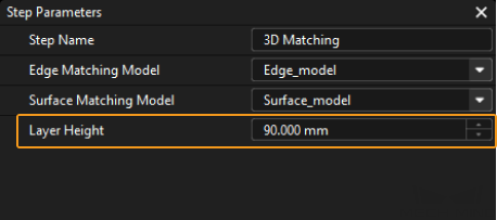
If there are object poses of other layers included in this range, you should adjust the value of Layer Height until there are only poses of objects on the highest layer within the range.
Adjust Turnover Box Poses
The Procedure is used to transform turnover box poses from the camera reference frame to the robot reference frame, adjust pose orientations, sort poses, and filter unqualified poses. There is no need to set parameters for this Procedure.
Output Turnover Box Poses
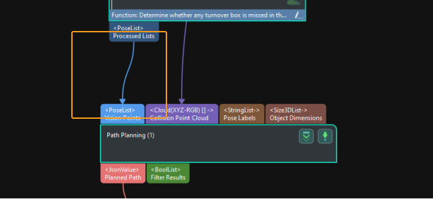
As Path Planning Step is used in the turnover box depalletizing solution for path planning, the turnover box poses are then input to the Path Planning Step. You can click the data flow to check relevant data.
So far, you have learned how to get started with turnover box locating.
Path Planning
The Path Planning Tool under the Path Planning Step is used in the turnover box depalletizing solution for path planning. Click Open the editor in the Step Parameters of Path Planning to open Path Planning Tool.
The process of path planning is shown in the figure below.

Configure Scene Objects
Scene objects are introduced to make the scene in the software closer to the real scenario, which facilitates the robot path planning. For specific operations, please refer to Configure Scene Objects.
Configure the Tool
The end tool should be configured so that its model can be displayed in the 3D simulation space and used for collision detection. For specific operations, please refer to Configure the Tool.
Adjust the Workflow
The workflow refers to the robot motion control program created in the form of a flowchart. After the scene objects and end tools are configured, you can adjust the workflow.
Adjust the Above-Bin Fixed Waypoint
-
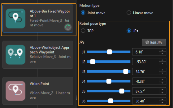
Select the “ Above-Bin Fixed Waypoint 1” Step, and then choose the “JPs” of the “Robot pose type” in the Step Parameters on the right. Then you can set the values of “JPs” according to the picking poses when the real robot is above the bin.
-
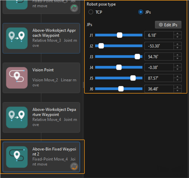
Select the “ Above-Bin Fixed Waypoint 2” Step, and then choose the “JPs” of the “Robot pose type” in the Step Parameters on the right. Then you can set the values of “JPs” according to the picking poses when the real robot is above the bin.
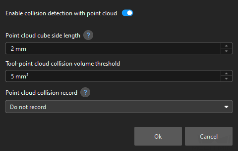
Configure Collision Detection
Collision configuration is used to detect and avoid possible collisions. By default, collisions between any two of the robot, tool, and scene objects will be detected. Once “Enable collision detection with point cloud” is enabled, the collision between the input point cloud and the tool will be detected.
Simulate and Run the Project
-
Click the Simulate button on the toolbar to simulate the Mech-Viz project.
-
If the simulation performance meets expectations, a Standard Interface program can be used to run the real robot.
Please refer to the picking example program and interface commands in Standard Interface communication to learn how to write the robot program.
|
It is recommended that the robot should move at a low speed and that you pay attention to the robot motion trajectory. In an emergency, press the emergency stop key on the teach pendant. |
So far, you have learned how to get started with the path planning.