Troubleshooting
This section introduces the common problems, possible causes, and solutions for the turnover box depalletizing solution.
Problem 1: 3D Matching Failure or Missed Turnover Box Recognition
Symptom
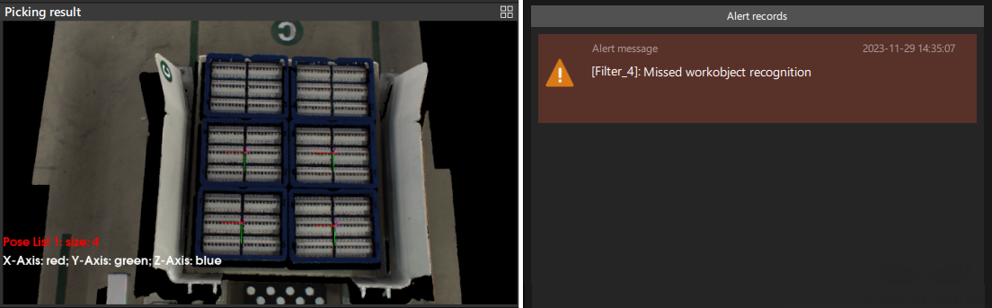
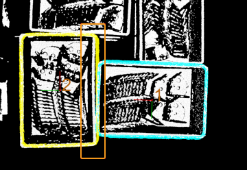
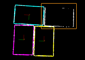
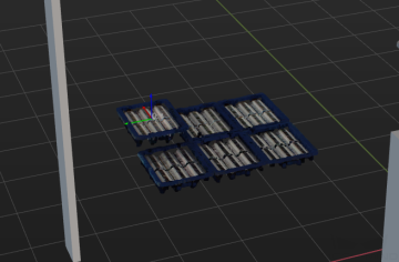
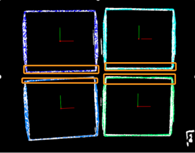
The “Picking sequence” area in the production interface displayed that the input image contained six turnover boxes, but only four turnover box poses were output (as shown in the left figure below), which triggered an alert saying that “Missed workobject recognition” (as shown in the right figure below) in the production interface.
Possible Causes
-
Due to incorrect setting of 3D ROI, the turnover box(es) is beyond the 3D ROI. Hence, no result can be output from the Mech-Vision project.
-
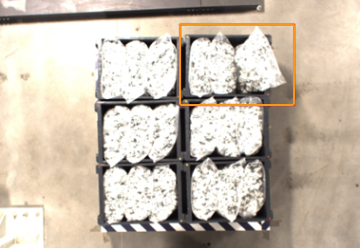
The material inside the turnover box obscured the top edge of the turnover box (as shown in the figure below), resulting in a low turnover box pose score from 3D matching and no output from the Mech-Vision project.
-
There was severe deformation in the turnover box, or a large difference in the size of the turnover box, which was significantly different from the point cloud model, resulting in a low turnover box pose score from 3D matching and no output from the Mech-Vision project.
-
The turnover box point cloud was in poor quality (as shown in the figure below), resulting in a low turnover box pose score from 3D matching and no output from the Mech-Vision project.
-
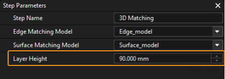
The parameter of Layer Height in the Turnover Box Poses of the Highest Layer Step was not set correctly.
-
The robot is mounted on the ceiling or on a slope.
Solutions
-
Reset 3D ROI based on workstation layout and pallet pattern dimensions, so that the turnover box will be within the ROI.
-
Regulate incoming material, so that it does not extend beyond the turnover box and does not obscure the top edge of the turnover box.
-
Make sure that there is no deformation of the turnover box in the process of real production. Eliminate the deformed turnover box.
-
To acquire qualified point cloud, it is recommended to use Mech-Eye Viewer to adjust camera exposure. For detailed adjustments, please refer to Problem 2.
-
Adjust the parameter of Layer Height to the standard height of turnover box.
-
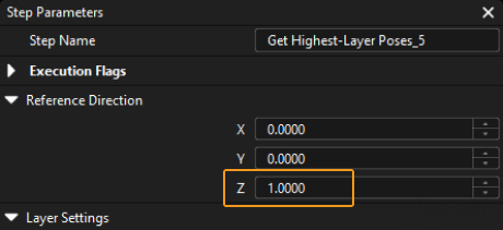
If the robot is mounted on a slope, you should obtain the pose of turnover box on the highest layer in the camera reference frame.
First, delete Transform Poses Steps before and after Step Get Highest-Layer Poses in the 3D Matching Procedure, and then connect Get Highest-Layer Poses Step and Merge Data Step.
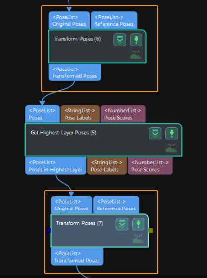
Then go to the Step Parameters panel of Obtain Poses of Turnover Boxes on the Highest Layer, set Z value of Reference direction to -1.
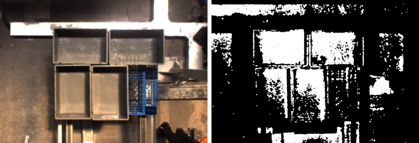
Problem 2: Poor Quality of Turnover Box Point Cloud
Symptom
The obtained turnover box point cloud was in poor quality. As shown in the figure below, the left figure is the 2D image of turnover box and the right figure is the point cloud of turnover box.
Possible Causes
-
The ambient light on site was too strong.
-
The setting of camera 3D exposure parameter was not proper.
Solutions
-
When the ambient light is too strong, it is recommended to use longer exposure time to enhance the image quality. When the ambient light is too strong and it is not effective to increase the exposure time, you can consider shading the station so that the ambient light intensity at the station remains constant.
-
As the captured image tends to be too bright when the turnover box is white, it is recommended to use shorter exposure time; as the captured image tends to be too dark when the turnover box is black, it is recommended to use longer exposure time.
-
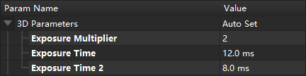
When there are turnover boxes with different colors, it is recommended to capture images using the method of combining shorter exposure time and longer exposure time, that is, set two exposures in Mech-Eye Viewer as shown below.
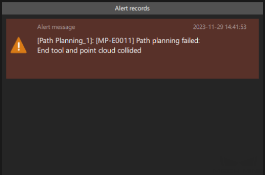
Problem 3: Path Planing Failure Resulting in Tool Colliding with Point Cloud
Symptom
The path planning failed, and the alert message saying that “tool collided with point cloud” appeared in the production interface.
Possible Causes
-
As the material exceeded the top edges of turnover box, the robot collided with material when the robot simulated picking the turnover box.
-
When the robot simulated picking the turnover box, it detected that the collision volume between the end tool and the point cloud exceeded the Collision Volume Threshold.
Problem 4: Too Much Point Cloud Noises in Mech-Viz or Presence of Scene Point Cloud Unrelated to Picking
Symptom
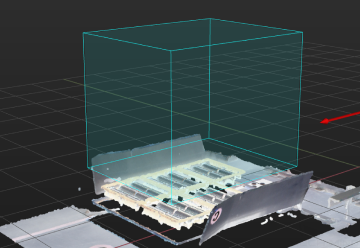
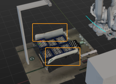
There were too much noises in the point cloud sent to Mech-Viz, or there were scene point cloud that was not relevant to picking (except ROI).
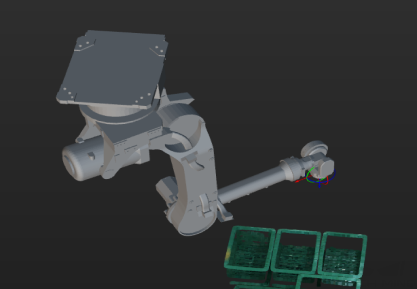
Take the following figure as an example, scene point cloud that was unrelated to picking was displayed in the Mech-Viz 3D simulation area.
Solutions
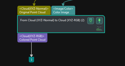
As in the From Cloud (XYZ-Normal) to Cloud (XYZ-RGB) Step, the prepossessed point cloud is input into the first input port, you need to connect the Send Point Cloud to External Service Step to send the prepossessed point cloud to Mech-Viz.
As shown in the figure below, the Colored Point Cloud output port of this Step is connected to the Collision Point Cloud input port of the Path Planning Step.
After point cloud preprocessing, the point cloud in the Mech-Viz 3D simulation area is shown in the figure below. The scene point cloud that is unrelated to picking is removed.
Problem 5: Possible Collision between the Gripper and Turnover Boxes When Picking
Symptom
When the robot picked the turnover boxes, it was possible for the gripper to collide with the turnover boxes.
Possible Causes
During the picking process of the robot, the gripper needs to reach into the gap between two neighboring turnover boxes (as shown in the figure below), and thus is prone to collision.
Solutions
To avoid the collision, Mech-Viz is needed for collision detection. The configuration method is shown below.
-
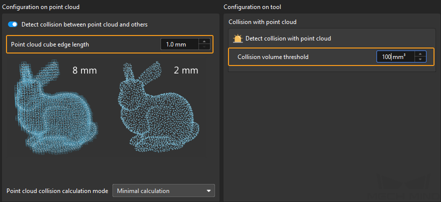
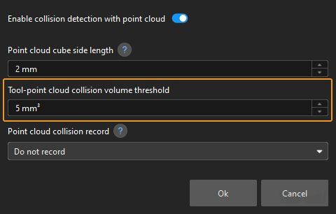
After importing the gripper model into the Mech-Viz, click Collisions at the bottom of the panel, and then click Collision detection configuration at its top.
-
In the “Collision Detection Configuration” window, select Detect collision between held workobject and others, and then set Point cloud cube edge length and Collision volume threshold according to actual situation.