Height Correction
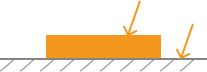
This tool is used to correct the height error in the profile, which is caused by the rotation of the laser profiler around the X-axis.
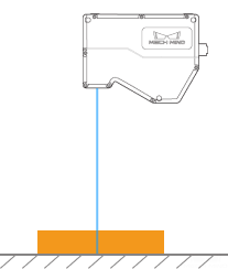
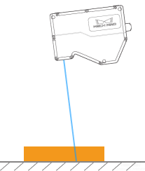
As shown below, the rotation of the laser profiler around the X-axis make the height difference between two locations in the acquired profile differ from the actual difference.
| Not rotated | Rotated around the X-axis | |
|---|---|---|
Laser profiler |
|
|
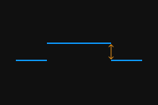
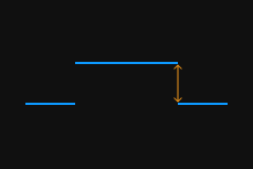
Acquired profile |
|
|
In the scan mode, click Edit to the right of Height Correction in the Parameters tab to open the Height Correction tool.
Prerequisites
In order to perform height correction, the following prerequisites must be satisfied:
-
It is recommended to use a target object with known dimensions and flat surfaces, such as a gauge block, and place the target object on a horizontal surface.
-
A relatively complete profile of the target object can be acquired. If the profile is incomplete, please refer to Profile Mode and adjust the other parameters first.
-
Keep the target object still relative to the laser profiler.
-
Select two surfaces (such as the top surface of the gauge block and the horizontal surface on which the gauge block is placed) for calculating the height difference, and determine the actual height difference of the two surfaces.
Instructions
Follow these steps to perform height correction:
-
Double-click Edit to the right of Height Correction to open the Height Correction window.
-
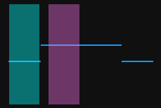
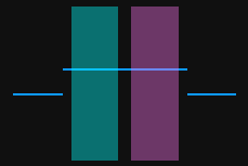
Select the detection areas and drag to adjust their positions. Make sure to satisfy the following criterion while adjusting:
The profile segments selected by the two detection areas should correspond respectively two the two surfaces used for calculating the height difference.
Two surfaces used for calculating the height difference
Detection areas
Correct
Incorrect
-
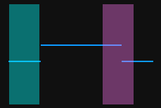
Select the detection areas and drag the handles on them to adjust their widths. Refer to the following criterion while adjusting:
With the above criterion satisfied, the detection areas can be as wide as possible to include more data for height correction.
-
In Actual height difference under Height differences, enter the actual height difference between the two surfaces.
The minimum value of Actual height difference is 0.01 mm, and the maximum value is the Z-axis measurement range of the laser profiler. -
Click Correct. The green line in the image area on the left represents the profile after height correction. Check if this profile satisfies your requirements:
-
If yes, click Apply to apply the height correction result and close the window.
-
If no, repeat steps 2 to 5.
-
-
Acquire data again in the profile mode and switch to Profile to check the effect of correction.