Provide Data Acquisition Control Signals with External Device
This topic introduces how to use an external device to provide the laser profiler with signals that control data acquisition, in order to obtain the intensity image, depth map, and point cloud from the laser profiler.
|
Relevant Input Signal Terminals
The following input signal terminals are discussed in this topic:
| No. | Name |
|---|---|
9 |
LEVELCONTROL_ENABLE |
10 |
MEASURE_START |
11 |
MEASURE_STOP |
The logic level of the LEVELCONTROL_ENABLE terminal signal determines the data acquisition control logic by the other two terminals. The following sections explain the two control logics. Please select the control logic that corresponds to your actual needs.
Control Data Acquisition with MEASURE_START Only
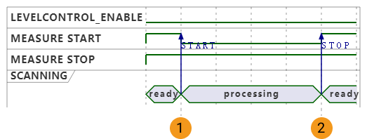
When the logic level of the LEVELCONTROL_ENABLE terminal signal is LOW, the MEASURE_STOP terminal does not participate in the control of data acquisition, and only the signals of the MEASURE_START terminal controls data acquisition.
-
Start data acquisition:
When the logic level of the MEASURE_START terminal signal changes from HIGH to LOW, the laser profiler is triggered to acquire data.
-
Stop data acquisition:
When the logic level of the MEASURE_START terminal signal changes from LOW to HIGH, the current round of data acquisition is stopped.
Even if the number of lines set in the Scan Line Count parameter has not been fully acquired, when a stop signal is received from an external device, the current round of data acquisition is stopped.
If you wish to end the data acquisition according to the value of Scan Line Count, please use the control logic when the logic level of the LEVELCONTROL_ENABLE terminal signal is HIGH.
|
Requirements on signal length:
|
Example
| No. | Data acquisition status | Signal logic level |
|---|---|---|
1 |
Data acquisition is started. |
MEASURE_START: changes from HIGH to LOW. |
MEASURE_STOP: remains HIGH. |
||
2 |
Data acquisition is stopped. |
MEASURE_START: changes from LOW to HIGH. |
MEASURE_STOP: remains HIGH. |
Connect Needed Terminals
If you want to control data acquisition with the MEASURE_START terminal only, connect the corresponding terminals according to the following rules:
-
Connect the LEVELCONTROL_ENABLE terminal, and keep the logic level of its signal LOW.
-
Connect the MEASURE_START terminal, and switch the logic level of its signal to LOW when you need to trigger data acquisition and to HIGH when you need to stop data acquisition.
Control Data Acquisition with MEASURE_START and MEASURE_STOP
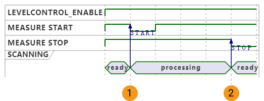
When the logic level of the LEVELCONTROL_ENABLE terminal signal is HIGH, the signals of both the MEASURE_START and MEASURE_STOP terminals control data acquisition.
-
Start data acquisition:
While the logic level of the MEASURE_STOP terminal signal remains HIGH, when the logic level of the MEASURE_START terminal signal changes from HIGH to LOW, the laser profiler is triggered to acquire data.
-
Stop data acquisition:
While the logic level of the MEASURE_START terminal signal remains LOW, when the logic level of the MEASURE_STOP terminal signal changes from HIGH to LOW, the current round of data acquisition is stopped.
Even if the number of lines set in the Scan Line Count parameter has not been fully acquired, when a stop signal is received from an external device, the current round of data acquisition is stopped. In this case, the acquired intensity image, depth map, and point cloud are incomplete.
|
Requirements on signal length:
|
Example
| No. | Data acquisition status | Signal logic level |
|---|---|---|
1 |
Data acquisition is started. |
MEASURE_START: changes from HIGH to LOW, and then changes back to HIGH. |
MEASURE_STOP: remains HIGH. |
||
2 |
Data acquisition is stopped. |
MEASURE_START: remains HIGH. |
MEASURE_STOP: changes from HIGH to LOW, and then changes back to HIGH. |
Connect Needed Terminals
If you want to control data acquisition with both the MEASURE_START and MEASURE_STOP terminals, connect the corresponding terminals according to the following rules:
-
Connect the MEASURE_START terminal, and switch the logic level of its signal to LOW when you need to trigger data acquisition.
-
If you want to acquire data according to the set value of Scan Line Count, then you do not need to connect the MEASURE_STOP terminal.
-
If you want to stop data acquisition with externally input signals, then you need to connect the MEASURE_STOP terminal, and switch the logic level of its signal to LOW when you need to stop data acquisition.
| The logic level of the LEVELCONTROL_ENABLE terminal signal is HIGH by default. Therefore, this terminal does not need to be connected. |
Next Steps
After selecting the control logic and connecting the hardware, please refer to Workflow of Triggering Data Acquisition and complete the other steps in order to trigger data acquisition with externally input signals.